Forming a protective sequence, Using servo alarm and alarm code outputs – Yaskawa FSP Amplifier User Manual
Page 128
FSP Amplifier User’s Manual
Chapter 5: Parameter Settings and Functions
5-61
Motor speed
(r/min)
/BK output
/S-ON input
Power OFF by /S-ON
(CN1-40)
input or alarm
occurrence
Servo ON
Servo OFF
Servomotor OFF
Stop by dynamic brake
or coast to a stop.
(Pn001.0)
Hold with brake
Pn508
Release
brake
Pn-507
Brake ON timing when the servomotor stops must be adjusted properly
because servomotor brakes are designed as holding brakes. Adjust the
parameter settings while observing equipment operation.
/BK Signal Output Conditions During Servomotor
Operation
The circuit is open under either of the following conditions:
• Motor speed drops below the setting at Pn507 after servo OFF.
• The time set at Pn508 has elapsed since servo OFF.
The actual speed used will be the maximum speed even if Pn507 is set
higher than the maximum speed.
5.5. Forming a Protective Sequence
This section describes the procedure for using I/O signals from the servo
amplifier to form a protective safety sequence.
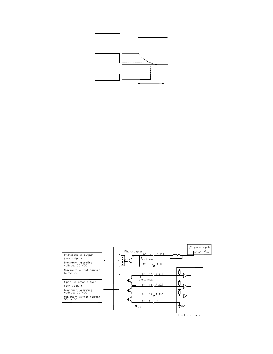
5.5.1. Using Servo Alarm and Alarm Code Outputs
The basic procedure for connecting alarm output signals is described
below.
FSP Amplifier