Selection of rotation direction – Yaskawa FSP Amplifier User Manual
Page 99
FSP Amplifier User’s Manual
Chapter 5: Parameter Settings and Functions
5-32
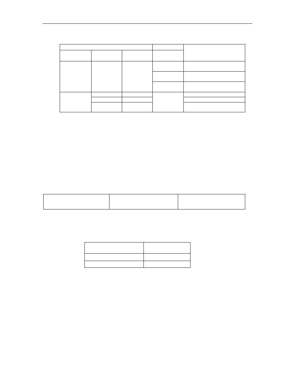
Use the following table when contact input speed control is used.
Contact Signal
Parameter
/P-CON
(/SPD-D)
/P-CL
(/SPD-A)
/N-CL
(/SPD-B)
Pn000.1
Selected Speed
3
Stopped by an internal
speed reference of 0.
4
Analog speed reference (V-
REF) input
— 0 0
6
Analog torque reference
input (torque control)
0
1
SPEED 1 (Pn301)
1
1
SPEED 2 (Pn302)
Direction of
rotation
0: Forward
1: Reverse
1 0
3, 4, 6,
Common
SPEED 3 (Pn303)
Note: 1.
0: OFF (high level); 1: ON (low level)
2.
Input signals indicated by the horizontal bar (-) are optional.
When contact input speed control is not used, input signals are used as
external torque limit inputs.
Note:
The contact input speed control function is used only when signals are allocated to /SPD-D, /SPD-A, and
/SPD-B.
Selection of Rotation Direction
The input signal /P-CON(/SPD-D) is used to specify the direction of the
servomotor rotation.
Ö Input /P-CON CN1-41
Speed Selection 1
(Forward External Torque Limit
Input)
Speed, Torque, and Position
Control
• When contact input speed control is used, the input signal /P-CON
(/SPD-D) specifies the direction of servomotor rotation.
/P-CON (/SPD-D) Input
Level
Signal Logic
0 Forward
rotation
1 Reverse
rotation
Note:
0: OFF (high level); 1: ON (low level)
• When contact input speed control is not used, the /P-CON signal is
used for proportional control, zero clamping, and torque/speed control
switching.
• Position Control is used here only by Pulse Reference, not by Serial
Command.