Yaskawa FSP Amplifier User Manual
Page 61
FSP Amplifier User’s Manual
Chapter 4: Trial Operation
4-6
Input Signal Status
LED Display
OFF (high level)
Top LED indicators light.
ON (low level)
Bottom LED indicators light.
Note: The servomotor will not operate properly if the following signal lines are not wired correctly. Short-circuit
the signal lines if they will be unused. Input signal selections (parameters Pn50A to Pn50D) can be used to
eliminate the need for external short-circuiting.
Signal Symbol
Connector Pin
Number
Description
P-OT CN1-42
The servomotor can rotate in forward direction
when this signal line is low (0V).
N-OT CN1-43
The servomotor can rotate in reverse direction
when this signal line is low (0V).
/S-ON CN1-40
The servomotor is turned ON when this signal
line is low (0V). Leave the servomotor OFF.
+24VIN CN1-47
Control power supply terminal for sequence
signals.
Note: IF an absolute encoder is being used, the servo will not turn ON when the servo ON signal (/S-ON) is input
unless the SEN signal is also ON.
When the SEN signal is checked in Monitor mode, the top of the LED will light because the SEN signal is
high when ON.
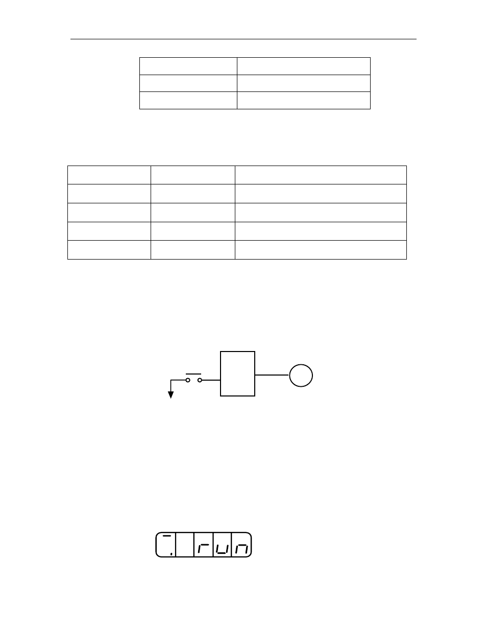
7. Turn ON the servo.
FSP Amplifier
CN1-40
Servomotor
Turn ON
0V
/S-ON
Turn ON the servo using the following procedure:
a) Make sure there are no reference signal inputs.
• Set V-REF (CN1-5) and T-REF (CN1-9) to 0V for speed and
torque control.
• Set PULS (CN1-7) and SIGN (CN1-11) to low for position
control.
b) Turn ON the servo ON signal.
Display with servo ON.