Sequence input circuit interface – Yaskawa FSP Amplifier User Manual
Page 46
FSP Amplifier User’s Manual
Chapter 3: Wiring
3-21
The following examples show how to select the pull-up resistor R1 so the
input current (I) falls between 7 and 15mA.
Application Examples
R1 = 2.2 kΩ with
V
CC
= 24 V ±5%
R1 = 1 kΩ with
V
CC
= 12 V ±5%
R1 = 180 Ω with
V
CC
= 5 V ±5%
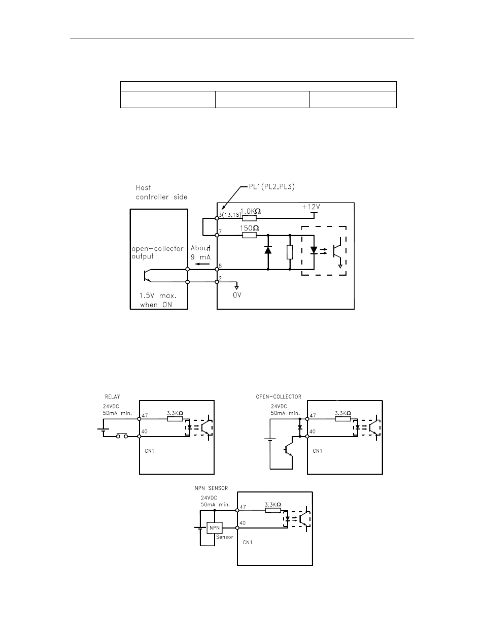
• Open-collector Output, Example 2: Using a servo amplifier with an
internal 12 V power supply
This circuit uses the 12 V power supply built into the servo amplifier.
The input is not isolated in this case.
FSP Amplifier side
CN1 terminals
Sequence Input Circuit Interface
The sequence input circuit interface connects through a relay, open-
collector transistor or NPN sensor circuit. Select a low-current relay;
otherwise a faulty contact will result.
FSP Amplifier
FSP Amplifier
FSP Amplifier