Settings according to host controller, Speed reference, Setting examples – Yaskawa FSP Amplifier User Manual
Page 79
FSP Amplifier User’s Manual
Chapter 5: Parameter Settings and Functions
5-12
5.2. Settings According to Host Controller
This section describes the procedure for connecting an FSP Amplifier to a host
controller, including the procedure for setting related parameters.
5.2.1. Speed Reference
Input the speed reference using the input signal: Speed Reference Input.
Since this signal has various uses, set the optimal reference input for the
system created.
FSP Amplifier
Torque
reference
Speed
reference
CN1-9
CN1-10
CN1-5
CN1-6
represents twisted-pair wires
P
P
P
Torque reference input
(analog voltage input)
Speed reference input
(analog voltage input)
Ö Input V-REF CN1-5
Speed Reference Input
Speed Control
Ö Input SG CN1-6
Signal Ground
Speed Control
The above inputs are used for speed control (analog reference). (Pn000.1 =
0, 4, 9, or A.) Always wire for normal speed control.
Refer to 7.1.6 Operation in Monitor Mode.
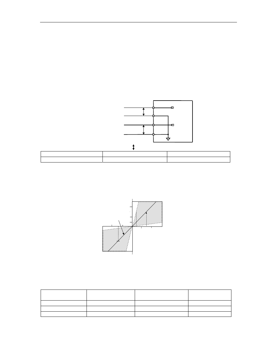
The motor speed is controlled
in proportion to the input voltage between V-REF and SG.
Rated m otor speed
Factory setting
-4
-8
-12
4
8
12
Input voltage (V)
Rated m otor s peed
The slope is set in Pn300.
Setting Examples
Pn300 = 600: This setting means that 6 V is equivalent to the rated motor
speed.
Speed Reference
Input
Rotation Direction
Motor Speed
SGMAH
Servomotor
+6 V
Forward rotation
Rated motor speed
3000 rpm
+1 V
Forward rotation
(1/6) rated motor speed
500 rpm
-3 V
Reverse rotation
(1/2) rated motor speed
1500 rpm
Parameter Pn300 can be used to change the voltage input range.