A.6. connecting mitsubishi's ad72 positioning unit – Yaskawa FSP Amplifier User Manual
Page 314
FSP Amplifier User’s Manual
Appendix A: Host Controller Connection Examples
A-7
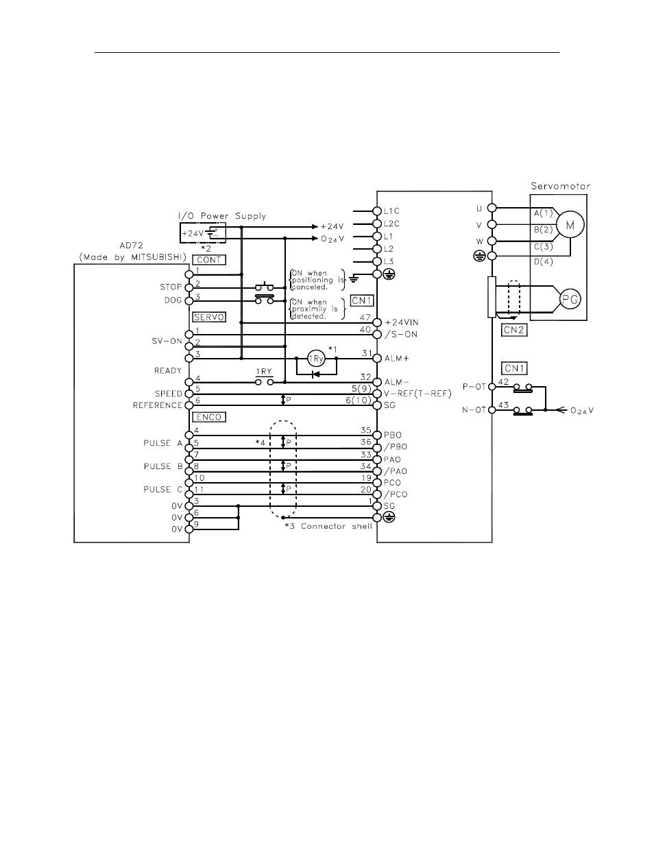
A.6. Connecting MITSUBISHI's AD72 Positioning Unit
The following diagram shows an example of connecting to the MITSUBISHI
AD72 Positioning Unit. In this example, the servo amplifier is used in Speed
Control Mode.
FSP Amp lifier
*1. The ALM signal is output for approximately two seconds when the power is turned ON. Take this into
consideration when designing the power ON sequence. The ALM signal actuates the alarm detection relay 1Ry to
stop main circuit power supply to the FSP Amplifier.
*2. Pin numbers are the same both for X-axis and Y-axis.
*3. Connect the connector wire of the cable to the connector shell.
*4. P indicates twisted pair wires.
Note: Only signals applicable to Mitsubishi's AD72 Positioning Unit and YEA's FSP Amplifier are shown here.