Using the /clt signal – Yaskawa FSP Amplifier User Manual
Page 76
FSP Amplifier User’s Manual
Chapter 5: Parameter Settings and Functions
5-9
Using the /CLT Signal
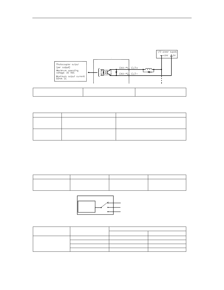
The following section describes the use of the contact output signal /CLT
as a torque limit output signal.
FSP Amplifier
Output Ö /CLT CN1-
*
1
Torque Limit Output
Speed, Torque, and
Position Control
This signal indicates whether the servomotor output torque (current) is
being limited.
Status
Conditions
Description
ON
The circuit between CN1-1 and 2
is closed.
CN1-1 is at low level.
Servomotor output torque is being limited.
(Internal torque reference is greater than the
limit setting).
OFF
The circuit between CN1-1 and 2
is open.
CN1-1 is at high level.
Servomotor output torque is not being
limited. (Internal torque reference is less
than the limit setting).
Settings: Pn402 (Forward Torque Limit)
Pn403 (Reverse Torque Limit)
Pn404 (Forward External Torque Limit): /P-CL input only
Pn405 (Reverse External Torque Limit): /N-CL input only
When the /CLT signal is used, the following parameter must be used to
select the output signal.
Parameter
Signal
Setting
Control Mode
Pn50F
Output Signal
Selections 2
Default Setting: 0000
Speed, Torque,
Position Control, and
Programming
CN1-25, 26 (SO1)
CN1-27, 28 (SO2)
CN1-29, 30 (SO3)
Pn50F.0
/CLT
Torque limit
detection
Output terminal
Use the following table to select which terminal will output the /CLT signal.
Output Terminal (CN1-)
Parameter Setting
*
1
*
2
0 — —
1 25 26
2 27 28
Pn50F.0
3 29 30
Note: Multiple signals allocated to the same output circuit are output using OR logic. Set other output signals to a
value other than the one allocated to the /CLT signal in order to use just the /CLT output signal. See 5.3.4
Output Circuit Signal Allocation.