Interface circuit, Sen signals – Yaskawa FSP Amplifier User Manual
Page 146
FSP Amplifier User’s Manual
Chapter 5: Parameter Settings and Functions
5-79
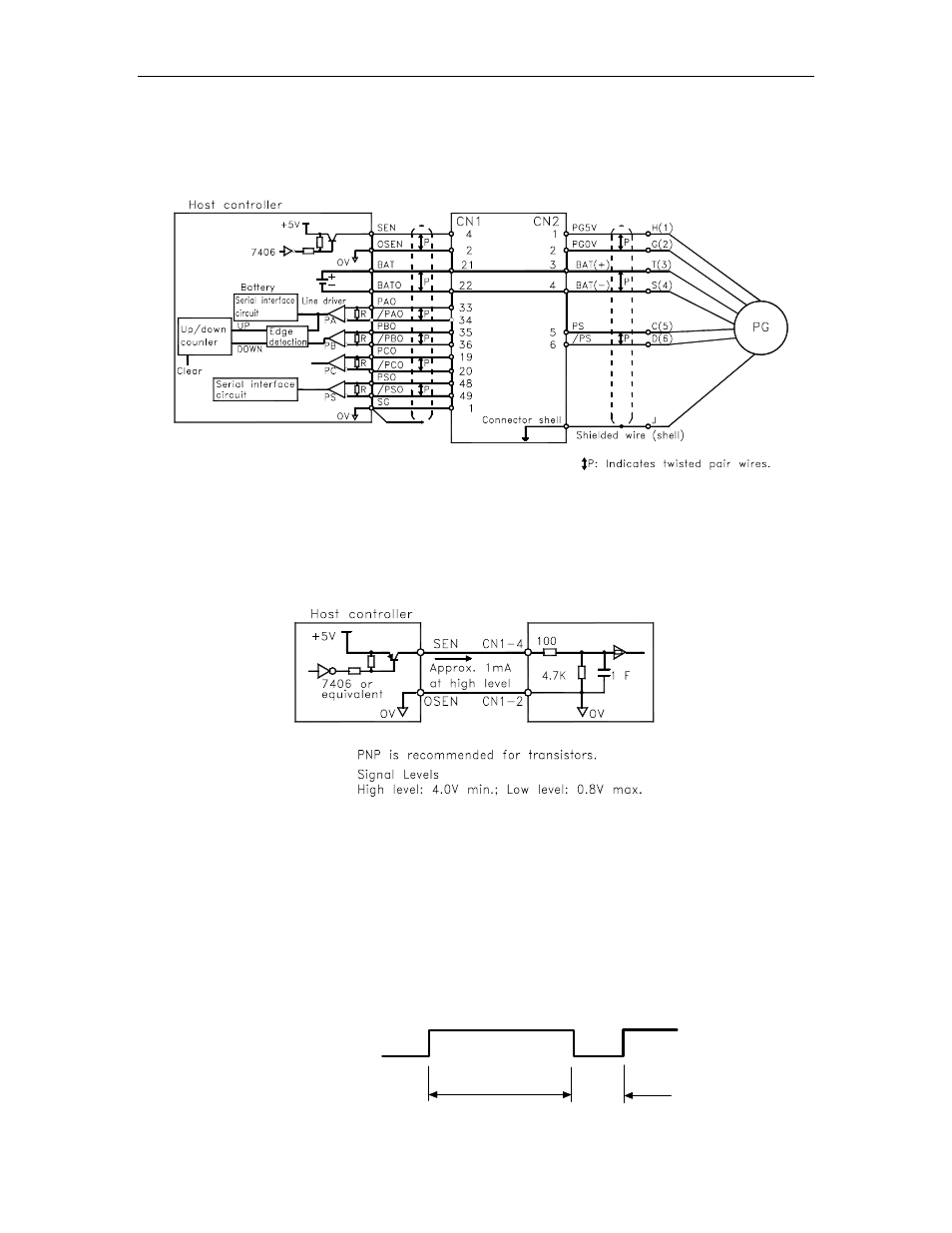
5.7.1. Interface Circuit
The following diagram shows the standard connections for an absolute
encoder mounted to a servomotor.
FSP Amplifier
Applicable line receivers: SN75175 or MC3486 by Texas Instruments.
Terminating resistance R: 220 to 470Ω
SEN Signals
Ω
μ
Ω
FSP Amplifier
• Wait at least three seconds after turning ON the power before raising
the SEN signal to high level.
• When the SEN signal is changed from low level to high level, the
multi-turn data and initial incremental pulses are transmitted.
• The motor cannot be operated until these operations are completed,
regardless of the status of the servo ON signal (/S-ON).
Note:
If for some reason it is necessary to turn OFF a SEN signal that is already ON, and then to turn it back ON
again, maintain the high level for at least 1.3 seconds before turning it ON and OFF.
OFF
ON = high level
OFF
ON
1.3 s min.
15 ms
min.
SEN signal