Yaskawa FSP Amplifier User Manual
Page 232
FSP Amplifier User’s Manual
Chapter 8: Ratings, Specifications and Dimensional Drawings
8-3
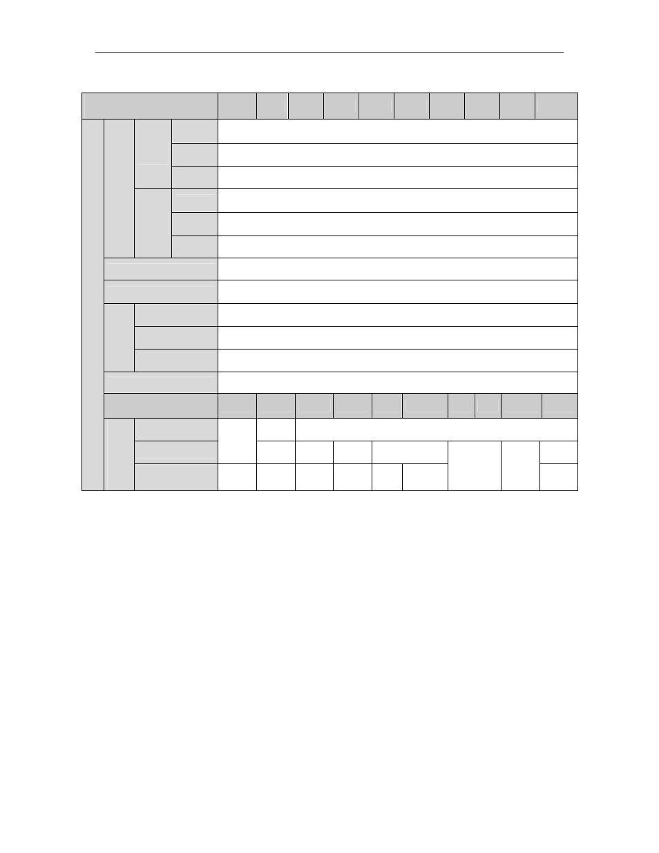
FSP Amplifier Ratings and Specifications (continued)
FSP Amplifier Model
FSP-
A3-01 02
04
05
08
10
15
20
30
50
100 V Single-phase 100 to 115 VAC +10 to -15%, 50/60 Hz *
200 V Single/Three-phase 200 to 230 VAC +10 to -15%, 50/60 Hz *
Main
Circuit
400 V Three-phase. 380 to 480 VAC +10 to -15%, 50/60 Hz
100 V Single-phase 100 to 115 VAC +10 to -15%, 50/60 Hz *
200 V Single-phase 200 to 230.5 VAC +10 to -15%, 50/60 Hz
Input P
o
w
e
r Sup
p
ly
*
Control
Circuit
400 V 24 VDC ±15%, 0.7 A
Control Method
Single or three-phase full-wave rectification IGBT-PWM (sine wave driven)
Feedback
Serial encoder: 13- (incremental only), 16-, or 17-bit (incremental/absolute).
Ambient/Storage
Temperature **
0 to +55°C/-20 to +85°C (When enclosed, internal temperatures must not exceed
this range.)
Ambient/Storage
Humidity
90% relative humidity or less (with no condensation)
C
ondit
ion
s
Vibration/Shock
Resistance
4.9 m/s
2
/ 19.6 m/s
2
Configuration
Base mounted (Rack mounted optional).
FSP Amplifier Model
FSP-
A3-01
02
04
05
08
10
15 20
30
50
For 100 V
1.1
(2.43)
—
For 200 V
0.8
(1.76)
0.8
(1.76)
1.1
(2.43)
— 1.7
(3.75)
—
Basi
c Spe
cif
ica
tion
s
Approx
. Ma
ss
[kg (l
b)]
For 400 V
—
—
—
1.7
(3.75)
—
1.7
(3.75)
2.8
(6.17)
3.8
(8.38)
5.5
(12.1)
* Supply voltage must not exceed 230 V +10% (253 V). A step-down transformer is required if the voltage exceeds
these values.
**Use the servo amplifier within the ambient temperature range. When enclosed, internal temperatures must not exceed
the specified range.