Cn2 encoder connector terminal layout, Cn2 connector models – Yaskawa FSP Amplifier User Manual
Page 50
FSP Amplifier User’s Manual
Chapter 3: Wiring
3-25
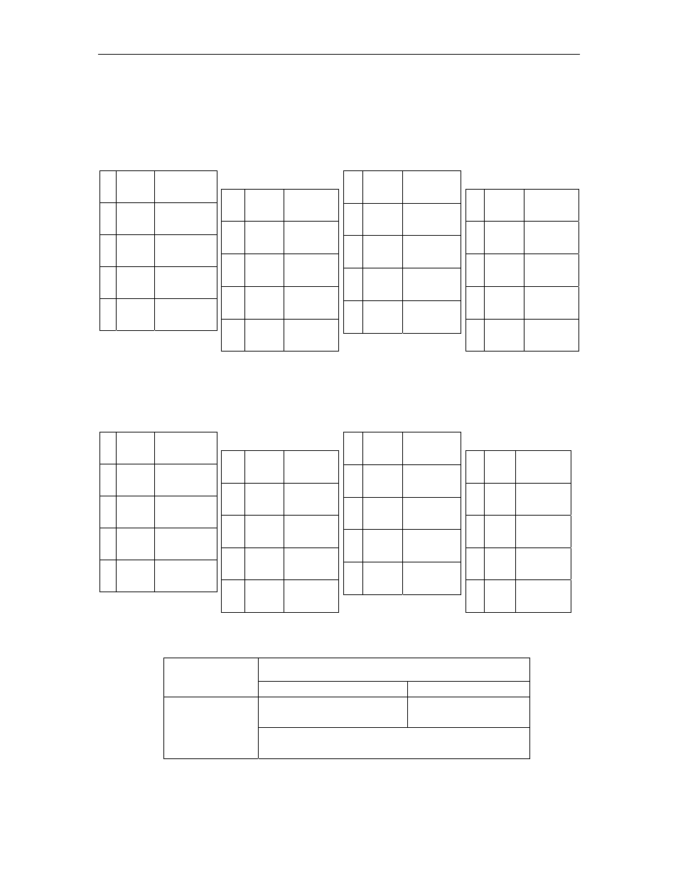
3.5.2. CN2 Encoder Connector Terminal Layout
The following tables describe CN2 connector terminal layout and types.
CN2 Connector Terminal Layout for the standard FSP
Amplifier (models FSP-MC
1 PPG0V PG
GND
3 PPG0V PG
GND
5 PPG5V
PG
+5V
7 NC*
—
9 /PS
Serial PG
/S-phase
2 PPG0V PG
GND
4 PPG5V PG
+5V
6 PPG5V PG
+5V
8 PS
Serial PG
S-phase
10 SPG5V
Serial PG
+5V
11 SPG0V
Serial PG
GND
13
BAT-
Battery -
input
15
/PC
PG
/C-phase
17
/PA
PG
/A-phase
19
/PB
PG
/B-phase
12 BAT+
Battery +
input
14 PC
PG
C-phase
16 PA
PG
A-phase
18 PB
PG
B-phase
20 NC*
—
Note: NC* – Leave contact open.
CN2 Connector with Commutation Sensors Terminal
Layout for Hall Effect FSP Amplifiers (models
FSP-MH)
1 PPG0V PG
GND
3 PPG0V PG
GND
5 PPG5V
PG
+5V
7 /UIN
U – Phase
Hall Effect
9 /VIN
V – Phase
Hall Effect
2 PPG0V PG
GND
4 PPG5V PG
+5V
6 PPG5V PG
+5V
8 NC*
—
10 SPG5V
+5V
11 SPG0V GND
13
BAT-
Battery -
input
15
/PC
PG
/C-phase
17
/PA
PG
/A-phase
19
/PB
PG
/B-phase
12 BAT+
Battery +
input
14 PC
PG
C-phase
16 PA
PG
A-phase
18 PB
PG
B-phase
20 /WIN
W – Phase
Hall Effect
Note: NC* – Leave contact open.
CN2 Connector Models
Applicable Plug (or Socket)
FSP Amplifier
Internal
Connector
Soldered Plug
Case
10120-3000VE 20PIN
10320-52A0-008
10220-52A2JL
20 PIN
YEA P/N: DTCR6973
Previous P/N: DE9406973