1 wiring main circuit, 1 names and descriptions of main circuit terminals, 1 wiring main – Yaskawa SGDS Sigma III Servo Amplifier User Manual
Page 105: 1 names and, 1 wiring main circuit -2, Caution
5 Wiring
5.1.1 Names and Descriptions of Main Circuit Terminals
5-2
5.1 Wiring Main Circuit
This section describes typical examples of main circuit wiring, functions of main circuit terminals, and the power
ON sequence.
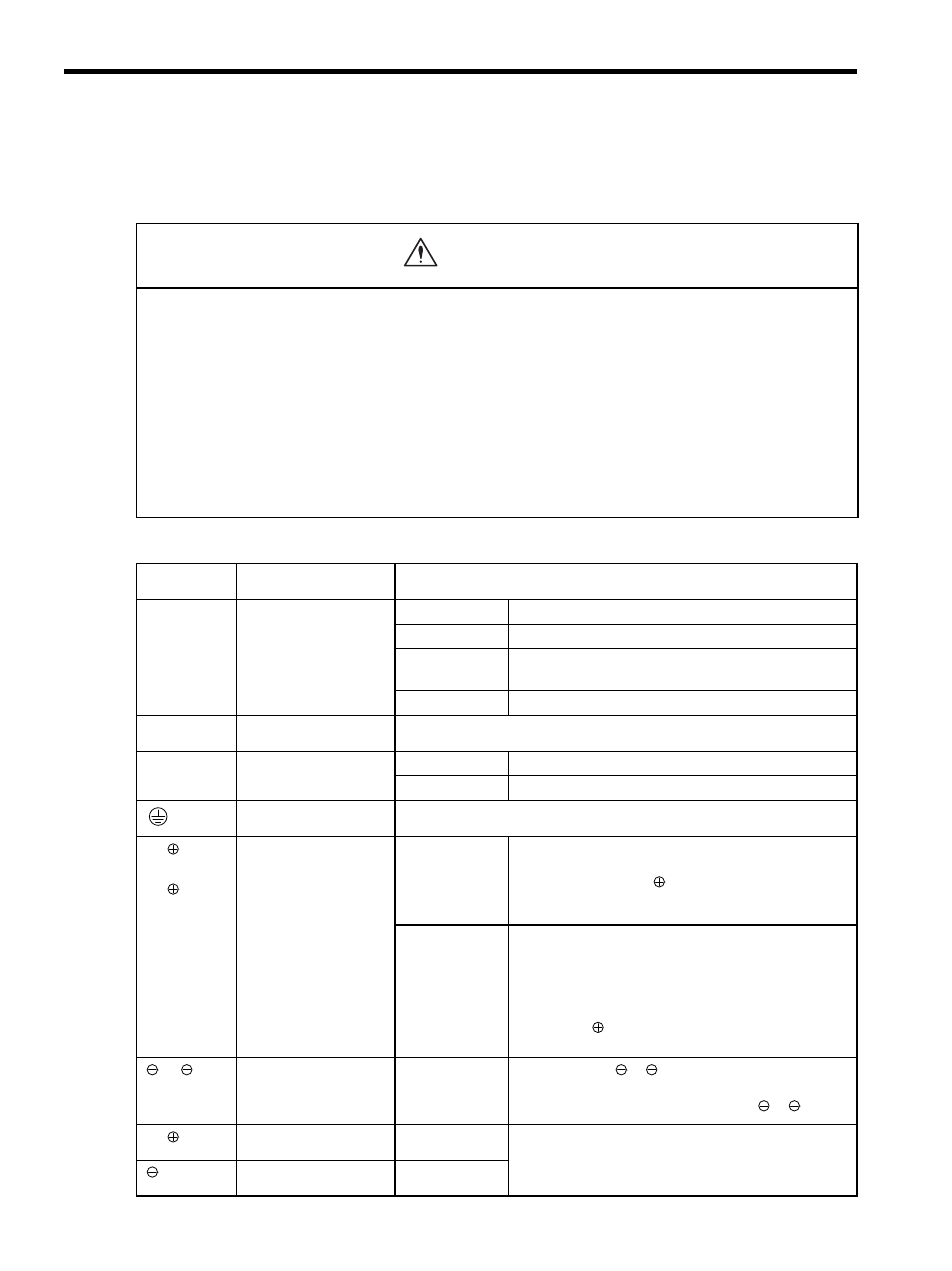
5.1.1 Names and Descriptions of Main Circuit Terminals
• Do not bundle or run power and signal lines together in the same duct. Keep power and signal lines
separated by at least 30 cm (11.81 inches).
• Use twisted-pair wires or multi-core shielded-pair wires for signal and encoder (PG) feedback lines.
The maximum length is 3 m (118.11 inches) for reference input lines and is 20 m (787.40 in) for PG feedback lines.
• Do not touch the power terminals for five minutes after turning power OFF because high voltage may still
remain in the SERVOPACK.
Make sure the charge indicator is out first before starting an inspection.
• Avoid frequently turning the power ON and OFF. Do not turn the power ON or OFF more than once per
minute.
Because the SERVOPACK has a capacitor in the power supply, a high charging current flows for 0.2 seconds when the
power is turned ON. Frequently turning the power ON and OFF causes main power devices like capacitors and fuses to
deteriorate, resulting in unexpected problems.
Terminal
Symbol
Name
Description
L1, L2
or
L1, L2, L3
Main circuit input
terminal
50 W to 400 W
Single-phase 100 to 115 V
+10%
,
-15%
(50/60 Hz)
50 W to 400 W
Single-phase 200 to 230 V
+10%
,
-15%
(50/60 Hz)
800 W
Single-phase 200 to 230 V
+10%
,
-15%
(50/60 Hz)
Note: L3 terminal is not used. Do not connect.
1.0 to 3.0 kW
Three-phase 200 to 230 V
+10%
,
-15%
(50/60 Hz)
U, V, W
Servomotor connection
terminals
Connects to the servomotor.
L1C, L2C
Control power input
terminal
50 W to 400 W
Single-phase 100 to 115 V
+10%
,
-15%
(50/60 Hz)
50 W to 3.0 kW
Single-phase 200 to 230 V
+10%
,
-15%
(50/60 Hz)
Ground terminals (×2)
Connects to the power supply ground terminals and servomotor ground
terminal.
B1/
, B2
or
B1/
, B2, B3
External regenerative
resistor terminal
50 W to 400 W
Normally not connected.
Connect an external regenerative resistor (provided by
customer) between B1/
-B2 if the regenerative capacity
is insufficient.
Note: B3 terminal is not provided.
1.0 to 3.0 kW
Normally short B2 and B3 (for an internal regenerative
resistor). Customers must provide external regenerative
resistor.
Remove the wire between B2 and B3 and connect an
external regenerative resistor (provided by customer)
between B1/
and B2 if the capacity of the internal
regenerative resistor is insufficient.
1, 2
DC reactor terminal
connection for power
supply harmonic wave
countermeasure
1.0 to 3.0 kW
Normally short
1-
2.
If a countermeasure against power supply harmonic waves
is needed, connect a DC reactor between
1-
2.
B1/
Main circuit plus
terminal
50 W to 3.0 kW
Use for DC power input (Refer to 5.1.3 (4)).
Main circuit minus
terminal
50 W to 400 W
CAUTION