2 using the mode switch (p/pi switching), 1) selecting the mode switch setting, 2 using the mode switch (p/pi switching) -24 – Yaskawa SGDS Sigma III Servo Amplifier User Manual
Page 251
8 Adjustments
8.6.2 Using the Mode Switch (P/PI Switching)
8-24
8.6.2 Using the Mode Switch (P/PI Switching)
Use the mode switch (P/PI switching) function in the following cases:
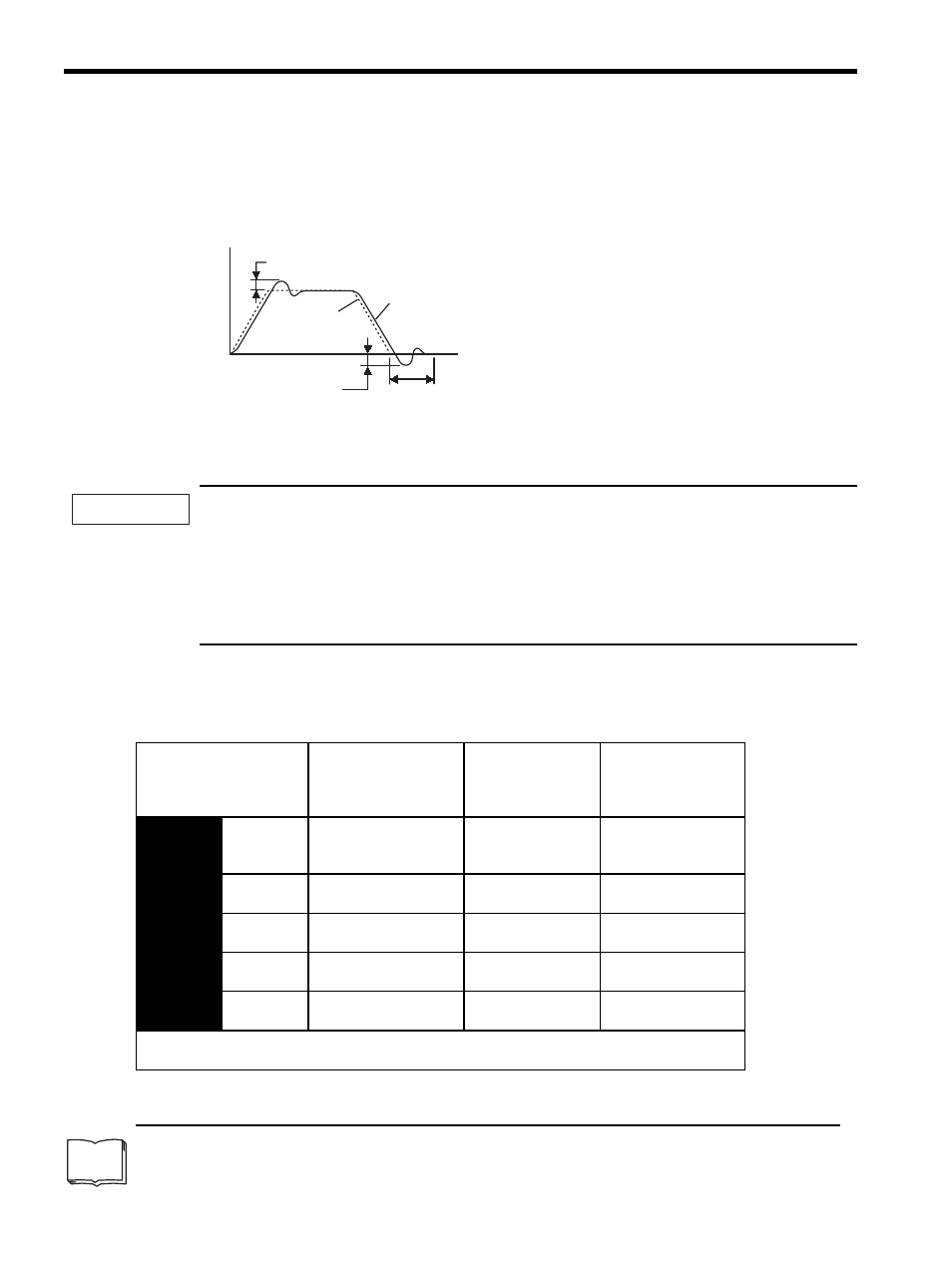
• To suppress overshooting during acceleration or deceleration (for speed control)
• To suppress undershooting during positioning and reduce the settling time (for position control)
The mode switch function automatically switches the speed control mode from PI control mode to P control
1
mode based on a comparison between the servo’s internal value and a user-set detection level.
1. The mode switch function is used in very high-speed positioning when it is necessary to use the
servodrive near the limits of its capabilities. The speed response waveform must be observed to adjust
the mode switch.
2. For normal use, the speed loop gain and position loop gain set by autotuning provide sufficient speed/
position control. Even if overshooting or undershooting occur, they can be suppressed by setting the host
controller’s acceleration/deceleration time constant, the SERVOPACK’s Soft Start Time Constants
(Pn305, Pn306), or Position Reference Acceleration/Deceleration Time Constant (Pn216).
(1) Selecting the Mode Switch Setting
The SERVOPACK provides the following four mode switch settings (0 to 3). Select the appropriate mode switch
setting with parameter Pn10B.0.
1
From PI control to P control
PI control means proportional/integral control and P control means proportional control. In short, switching “from PI
control to P control” reduces effective servo gain, making the SERVOPACK more stable.
Actual servomotor operation
Overshoot
Speed
Reference
Setting time
Time
Undershoot
TERMS
IMPORTANT
Parameter
Mode Switch
Selection
Parameter
Containing
Detection Point
Setting
Setting Units
Pn10B
n.
0
Use a torque reference
level for detection point.
(Factory setting)
Pn10C
Percentage of rated
torque:
%
n.
1
Use a speed reference
level for detection point.
Pn10D
Motor speed: RPM
n.
2
Use an acceleration
level for detection point.
Pn10E
Motor acceleration:
10 (RPM)/s
n.
3
Use an error pulse level
for detection point.
Pn10F
Reference unit
n.
4
Do not use mode switch
function.
−
−
Selects a condition in which to execute mode switching (P/PI switching). The setting is validated
immediately.