1) cn6a and cn6b connectors terminal layout, 2) cn6a and cn6b specifications, 3 precautions for wiring mechatrolink ii cables – Yaskawa SGDS Sigma III Servo Amplifier User Manual
Page 117: 1) number of stations, 2) cables, 3) cable length, 4) cable length between stations, 2 mec, 3 pre
5 Wiring
5.4.2 MECHATROLINK II Communications Connectors (CN6A, CN6B)
5-14
5.4.2 MECHATROLINK II Communications Connectors (CN6A, CN6B)
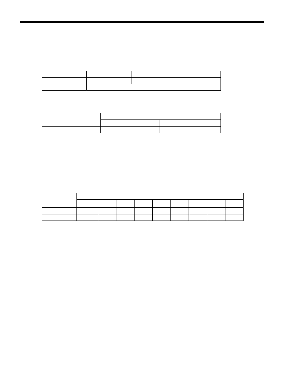
The terminal layout and specifications of the CN6A and CN6B connectors are shown below.
(1) CN6A and CN6B Connectors Terminal Layout
Note: The connector shell is connected to the FG (frame ground).
(2) CN6A and CN6B Specifications
5.4.3 Precautions for Wiring MECHATROLINK II Cables
Observe the following precautions when wiring MECHATROLINK II cables.
(1) Number of Stations
The number of stations is determined by the settings for the transmission cycle and number of transmission bytes.
When the communications retry channel is set to 1, the C2 master is not connected and the number of stations
possible is as follows for the combinations of transmission cycle and transmission bytes
.
* When the transmission cycle is 0.25 ms, set the communications cycle in multiples of 0.5
ms.
Note: 1. When the number of stations actually connected is less than the max. number of
stations, the remaining channels can be used as communications retry channels.
(Number of communications retry channels = Max. number of stations - Number of
actual stations connected+1)
2. When not using communications retry, the max. number of stations is increased by
one.
3. When connecting the C2 master, the max. number of stations is decreased by one.
(2) Cables
Be sure to use the specified cables.
For more information on cables, refer to 4.4.10 MECHATROLINK/MECHATROLINK II Communication Cable,
4.4.11 MECHATROLINK/MECHATROLINK II Terminator.
(3) Cable Length
The total cable length must be 50 m or less.
(4) Cable Length between Stations
The length of the cable between stations must be 0.5 m or more.
1
2
3
4
−
/S
S
SH
Not connected
Serial data I/O
Not connected
Specifications for SERVO-
PACK Connectors
Applicable Plug (or Socket)
Connector (on Cable)
Manufacturer
DUSB-ARA41-T11
DUSB-APA41-B1-C50
DDK Ltd.
Table 5.1 Transmission Cycle, Transmission Bytes, and Max. Number of Stations
Transmission
Bytes
Transmission Cycle
0.25 ms
∗
0.5 ms 1.0 ms 1.5 ms 2.0 ms 2.5 ms 3.0 ms 3.5 ms 4.0 ms
17
2
6
14
23
30
30
30
30
30
30
0
3
8
14
20
25
30
30
30