Yaskawa SGDS Sigma III Servo Amplifier User Manual
Page 332
11.2 List of Parameters
11-17
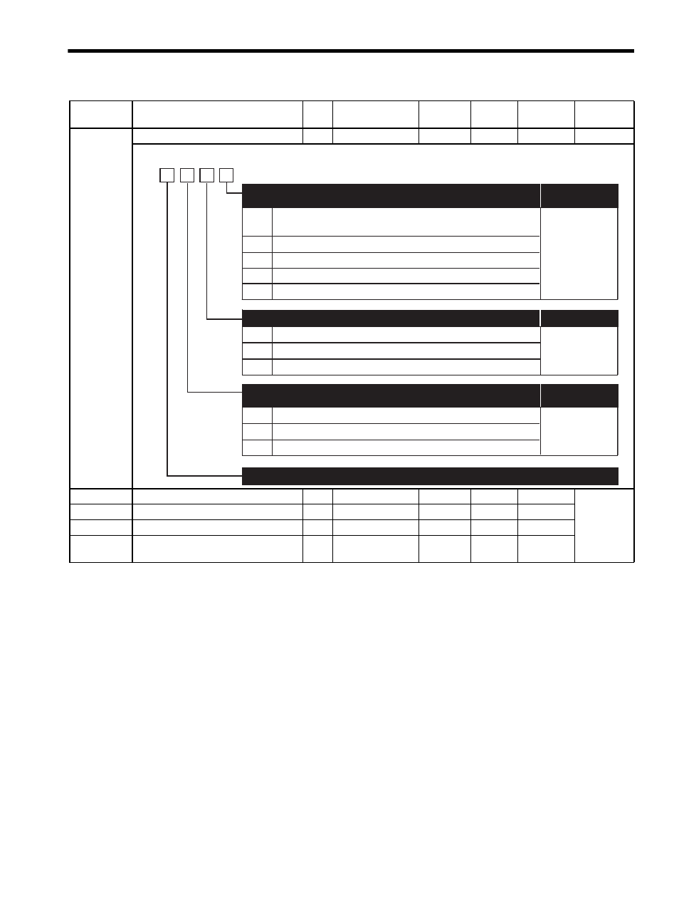
Pn10B
Gain Related Application Switch
2
−
−
0000
∆/
Pn10C
Mode Switch (torque reference)
2
0 to 800%
1%
200%
Pn10D
Mode Switch (speed reference)
2
0 to 10000 RPM
1 RPM
0 RPM
Pn10E
Mode Switch (acceleration)
2
0 to 30000 RPM/ s 1 RPM/ s 0 RPM/ s
Pn10F
Mode Switch (error pulse)
2
0 to 10000
reference units
1 refer-
ence unit
0 refer-
ence unit
Note:
: Can be changed at any time, and immediately validated after changing. (Called an online
parameter.)
∆: Validated after a Set Up Device command is sent, when loading and using parameters at
power ON. Also validated when turning OFF and then ON the power supply again after a
Write Non-volatile Parameter (PPRM_WR) command is sent.
Parameter
No.
Name
Data
Size
Setting Range
Units
Factory
Setting
Changing
Method
Reference
Section
0
1
2
3
4
0
1
Uses internal torque reference as the switching condition
(Level setting: Pn10C)
Uses speed reference as the switching condition (Level setting: Pn10D)
Uses acceleration as the switching condition (Level setting: Pn10E)
Uses position error pulse as the switching condition (Level setting: Pn10F)
No mode switch function available
PI control
I-P control
Reserved (Do not change)
Mode Switch Selection
(Refer to "8.6.2 Using the Mode Switch (P/PI Switching).")
Speed Loop Control Method
Reserved (Do not change)
4th
digit
3rd
digit
2nd
digit
1st
digit
n.
2 and 3
0
1
2
Standard position control
Less deviation control
Less deviation control with reference filter
Position Loop Control Method
(Refer to "8.6.8 Less Deviation Control.")
∆
∆
Changing Method
Changing Method
Changing Method