6 switching gain settings, 1) manual gain switching setting, 2) switchable gain combinations – Yaskawa SGDS Sigma III Servo Amplifier User Manual
Page 257: 6 switching gain settings -30
8 Adjustments
8.6.6 Switching Gain Settings
8-30
The speed feedback compensation usually makes it possible to increase the speed loop gain and position
loop gain. Once the speed loop gain and position loop gain have been increased, the machinery may vibrate
significantly and may even be damaged if the compensation value is changed significantly or Pn110.1 is set
to “1” (i.e., speed feedback compensation disabled).
8.6.6 Switching Gain Settings
Two gain switching functions are available : manual gain switching that uses external input signals and automatic
gain switching that automatically switches the gain settings.
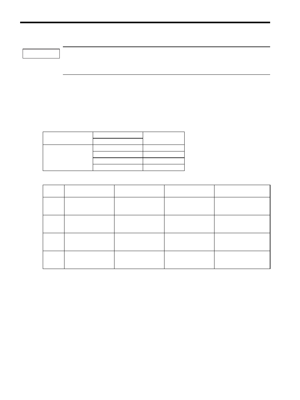
The manual gain switching function uses the settings of the external input G-SEL signal of the OPTION field to
switch between gain settings 1 through 4. The following table lists the switchable gain and related parameter.
(1) Manual Gain Switching Setting
(2) Switchable Gain Combinations
The Automatic Gain Switching switches the setting between the gain settings 1 and 2 shown in the above table
when the SERVOPACK status satisfies the “Switching Setting” conditions set in the parameter Pn139: From the
gain settings 1 to 2 when “Condition A” is established, and from the gain settings 2 to 1 when “Condition B” is
established.
“Switching Delay” stays unchanged if the switching condition is established. This function is effective when the
switching conditions are not stable or a precised timing setting is required. To minimize shocks at gain
switching, set “Switching Time” so that the gain can be changed smoothly in linear pattern. “Switching Delay”
and “Switching Time” can be set respectively for the switching from the gain switching 1 to 2 and from 2 to 1 as
shown in the table below.
IMPORTANT
Parameter Setting
Switching Setting
Setting
G-SEL
Pn139 = n.
0
Manual Gain Switching
00
Gain Setting 1
01
Gain Setting 2
10
Gain Setting 3
11
Gain Setting 4
Setting
Speed Loop Gain
Speed Loop Integral
Time Constant
Position Loop Gain
Torque Reference Filter
Gain
Settings
1
Pn100
Speed Loop Gain
Pn101
Speed Loop Integral
Time Constant
Pn102
Position Loop Gain
Pn401
Torque Reference Filter
Time Constant
Gain
Settings
2
Pn104
Speed Loop Gain #2
Pn105
Speed Loop Integral
Time Constant #2
Pn106
Position Loop Gain #2
Pn412
1st Step Torque Reference
Filter Time Constant #2
Gain
Settings
3
Pn12B
Speed Loop Gain #3
Pn12C
Speed Loop Integral
Time Constant #3
Pn12D
Position Loop Gain #3
Pn413
1st Step Torque Reference
Filter Time Constant #3
Gain
Settings
4
Pn12E
Speed Loop Gain #4
Pn12F
Speed Loop Integral
Time Constant #4
Pn130
Position Loop Gain #4
Pn414
1st Step Torque Reference
Filter Time Constant #4