Yaskawa SGDS Sigma III Servo Amplifier User Manual
Page 343

11 Appendix
11.2.2 List of Parameters
11-28
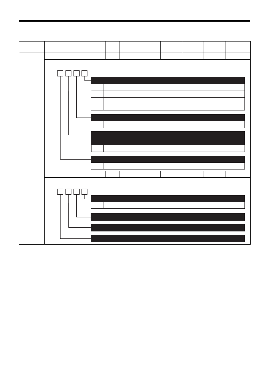
Pn50F
Output Signal Selection 2
2
−
−
0000
∆
Pn510
Output Signal Selection 3
2
−
−
0000
∆
Note:
∆: Validated after a Set Up Device command is sent, when loading and using parameters at
power ON. Also validated when turning OFF and then ON the power supply again after a
Write Non-volatile Parameter (PPRM_WR) command is sent.
Parameter
No.
Name
Data
Size
Setting Range
Unit
Factory
Setting
Changing
Method
Reference
Section
0
1
2
3
0 to 3
Do not use.
Outputs the signal from CN1-1, 2 output terminal.
Outputs the signal from CN1-23, 24 output terminal.
Outputs the signal from CN1-25, 26 output terminal.
Same as /CLT
Same as /CLT
Same as /CLT
/CLT Signal Mapping
/VLT Signal Mapping
/BK Signal Mapping
(Refer to "6.3.14 Apply Brake (BRK_ON : 21H), 6.3.15 Release Brake (BRK_OFF : 22H),
7.6.2 Using the Holding Brake.")
4th
digit
3rd
digit
2nd
digit
1st
digit
n.
0 to 3
0 to 3
/WARN Signal Mapping
0 to 3 Same as /CLT
/NEAR Signal Mapping
4th
digit
3rd
digit
2nd
digit
1st
digit
n.
Reserved (Do not change)
Reserved (Do not change)
Reserved (Do not change)