2 wiring for noise control, 1) wiring example, 2) correct grounding – Yaskawa SGDS Sigma III Servo Amplifier User Manual
Page 122: 2 wiring for, 2 wiring for noise control -19
5.6 Others
5-19
5.6.2 Wiring for Noise Control
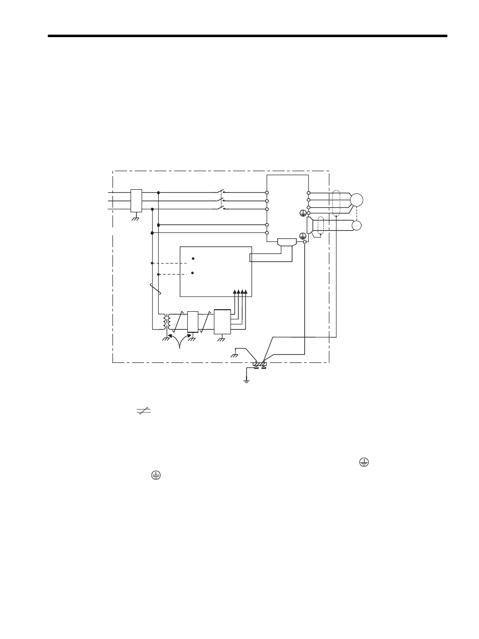
(1) Wiring Example
The SERVOPACK uses high-speed switching elements in the main circuit. It may receive “switching noise”
from these high-speed switching elements if wiring or grounding around the SERVOPACK is not appropriate. To
prevent this, always wire and ground the SERVOPACK correctly.
The SERVOPACK has a built-in microprocessor (CPU), so protect it from external noise as much as possible by
installing a noise filter in the appropriate place.
The following is an example of wiring for noise control.
(2) Correct Grounding
Always connect servomotor frame terminal FG to the SERVOPACK ground terminal
. Also be sure to ground
the ground terminal
.
If the servomotor is grounded via the machine, a switching noise current will flow from the SERVOPACK power
unit through motor stray capacitance. The above grounding is required to prevent the adverse effects of switching
noise.
For ground wires connected to the casing, use a thick wire with a thickness of
at least 3.5 mm (0.005 in ) (preferably, plain stitch cooper wire)
2
should be twisted-pair wires.
When using a noise filter, follow the precautions in (3) Using Noise Filter.
U
W
V
L2
L1
L3
L2C
L1C
CN2
CN1
SERVOPACK
Servomotor
Operation relay
sequence
Signal generation
circuit (provided by
customer)
1LF
AVR
(Ground)
(Casing)
(Casing)
(Casing)
2
(Casing)
(Ground plate)
2LF
3.5 mm
(0.005 in )
min.
2
200 VAC
Noise filter ∗3
∗3
∗1
∗1
∗2
∗3
∗1
∗2
2 mm
2
(0.003 in ) min.
3.5mm
(0.005 in ) min.
2
∗1
2.0 mm
2
(0.003 in )
min .
3.5mm
(0.005 in )
min.
2
PG
(FG)
M
2
2
Wires of 3.5 mm
(0.005 in ) or more
2
2
2
Ground: Ground to an independent ground
(at least class-3 grounding (100
Ω max.)
2
2
3.5mm
2
(0.0005in
2
)
min.
*1