4 settings according to host controller, 1 sequence i/o signals, 1) input signal connections – Yaskawa SGDS Sigma III Servo Amplifier User Manual
Page 202: 4 settings accord, 1 seque, 4 settings according to host controller -13, 1 sequence i/o signals -13, Important
7.4 Settings According to Host Controller
7-13
7.4 Settings According to Host Controller
This section describes the procedure for connecting a SGDS-
1
SERVOPACK to a host controller,
including the procedure for setting related parameters.
7.4.1 Sequence I/O Signals
Sequence I/O signals are used to control SERVOPACK operation. Connect these signal terminals as required.
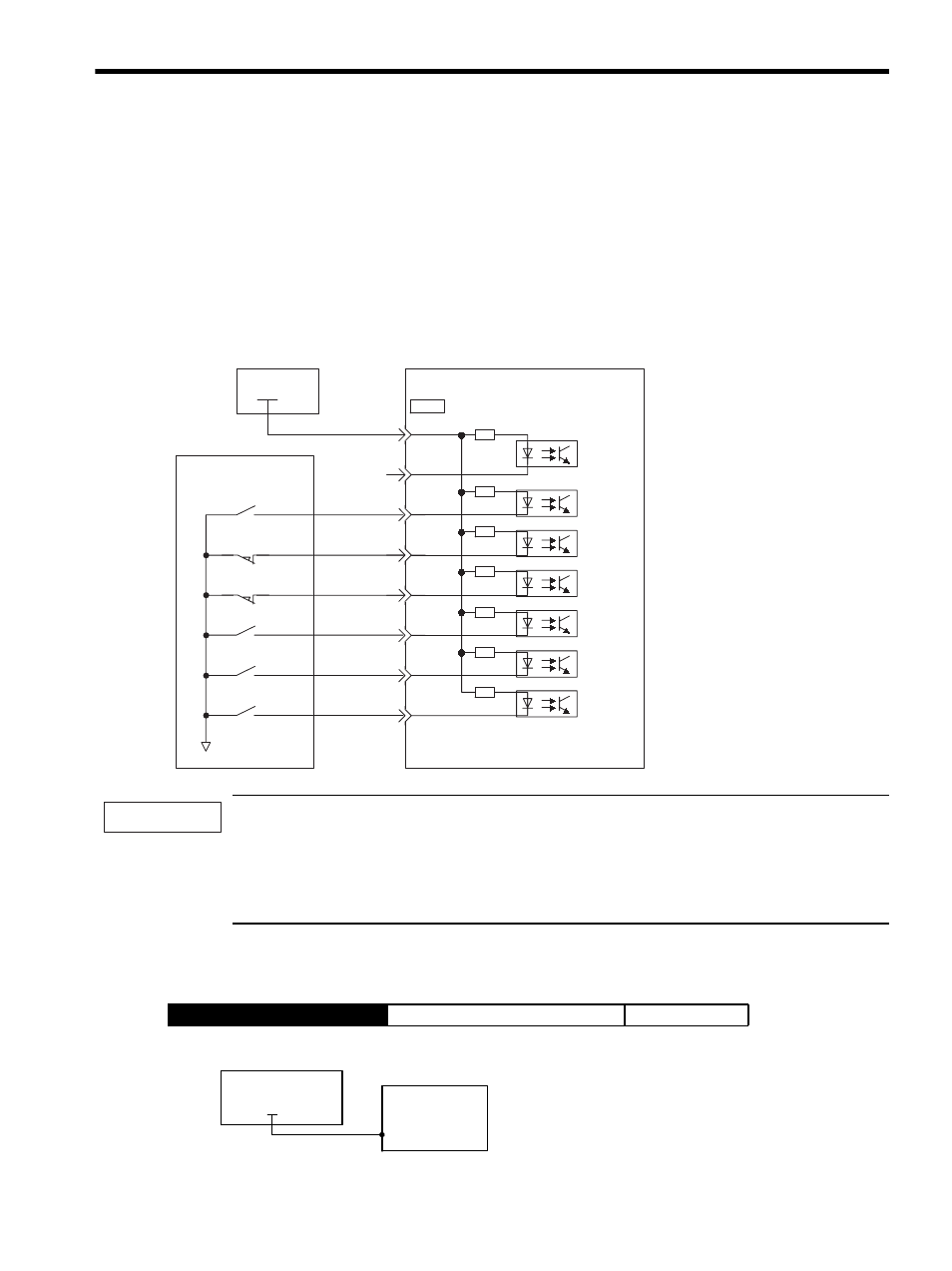
(1) Input Signal Connections
Connect the sequence input signals. (Factory settings)
Provide an external input power supply; the SERVOPACK does not have an internal 24-V power supply.
• External power supply specifications for sequence input signal: 24
± 1 VDC, 50 mA min.
Yaskawa recommends using the same external power supply as that used for output circuits. The allowable
voltage range for the 24-V sequence input circuit power supply is 11 to 25 V. Although a 12-V power supply
can be used, contact faults can easily occur for relays and other mechanical contacts under low currents.
Confirm the characteristics of relays and other mechanical contacts before using a 12-V power supply.
The function allocation for sequence input signal circuits can be changed.
Refer to 7.5.2 Input Circuit Signal Allocation for more details.
The external power supply input terminal is common to sequence input signals.
→ Input +24VIN CN1-6
External I/O Power Supply Input
Position Control
I/O power
supply
SERVOPACK
Photocoupler
Host controller
6
13
9
+24V
7
8
10
11
12
0 V
+24VIN
P - O T
N - O T
/EXT2
/EXT1
/DEC
/EXT3
3.3k
Ω
CN1
IMPORTANT
+ 24 V IN
CN1-6
Connect an external I/O power supply.
I/O power supply
+ 2 4 V
SERVOPACK