5 three-phase 200 v, 3.0~5.0kw, 3 servopack internal block diagrams – Yaskawa SGDS Sigma III Servo Amplifier User Manual
Page 68
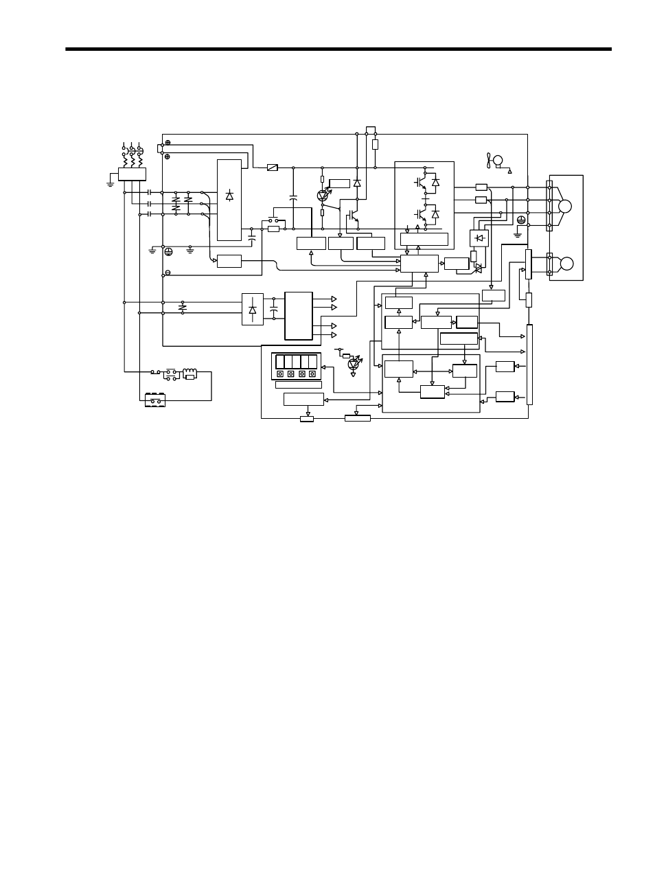
3.3 SERVOPACK Internal Block Diagrams
3-11
3.3.5 Three-phase 200 V, 3.0~5.0kW
Relay drive
PWM
generator
Voltage
sensor
Voltage
sensor
Gate drive
Interface
Current
sensor
Gate drive over-
current protection
DC/DC
converter
Digital
current
amp
Divider
Reference pulse
processing
Position
control
Speed
control
PG signal
processing
Current
reference
calculation
Analog voltage
converter
I/O
`
`
`
Monitor display
R2
A/D
XX3
XX1
XX2
L1
L2
L3
1MC
Noise filter
2
1
+
-
C1
FU1
P
N
R
S
T
+5V
±5V
±15V
+5V
±12V
0V
POWER
+
-
+
-
L1C
L2C
Power
OFF
Power
ON
1MC
1MC
Surge suppressor
Open during
servo alarm
(SRY)
FAN1
±12V
W
V
U
W
V
U
AC servomotor
CN2
CN8
For battery
connection
PG
ASIC
CN1
PG output
Sequence I/O
CPU
Serial port
P
N
CHARGE
+
-
B1
B2 B3
Gate drive
+
-
DB
+
-
CN3
CN5
Ry1
Analog monitor
output for supervision
Digital operator
personal computer
Speed and torque
reference input
+10%
-15%
Three-phase
200 to 250V
(50\60Hz)