1) adjustment procedure, Important – Yaskawa SGDS Sigma III Servo Amplifier User Manual
Page 256
8.6 Servo Gain Adjustment Functions
8-29
When this function is used, it is assumed that the moment of inertia ratio set in Pn103 is correct. Verify that
the moment of inertia ratio has been set correctly.
(1) Adjustment Procedure
The following procedure explains how to adjust when the speed loop gain cannot be increased due to vibrations
in the mechanical system. When adding a speed feedback compensation, observe the position error and torque
reference with the analog monitor (Refer to 8.7 Analog Monitor) while adjusting the servo gain.
1. Set parameter Pn110 to “0002” so that speed feedback compensation will be enabled and the normal
autotuning function will be disabled.
2. Make normal servo gain adjustments with no feedback compensation. With PI control, gradually increase
the Speed Loop Gain in Pn100 and reduce the Speed Loop Integral Time Constant Pn101, setting the Posi-
tion Loop Gain in Pn102 to the same value as that of the Speed Loop Gain in Pn100.
Use the result from the following equation as a initial estimate when setting the Speed Loop Integral Time
Constant in Pn101.
Speed loop gain units: 0.1 Hz
Check the units when setting the Speed Loop Integral Time Constant in Pn101. The value in Pn101 is set
in units of 0.01 ms.
Set the same value for the speed loop gain and position loop gain even though the speed loop gain units
(0.1 Hz) are different form the position loop gain units (0.1/s).
3. Repeat step 2 to increase the speed loop gain while monitoring the settling time with the analog monitor’s
position error and checking whether vibration occurs in the torque reference. If there is any vibrating
noise or noticeable vibration, gradually increase the Torque Reference Filter Time Constant in Pn401.
4. Gradually increase only the position loop gain. When it has been increased about as far as possible, then
decrease the Speed Feedback Compensation in Pn111 from 100
%
to 90
%
. Then repeat steps 2 and 3.
5. Decrease the speed feedback compensation to a value lower than 90
%
. Then repeat steps 2 through 4 to
shorten the settling time. If the speed feedback compensation is too low, however, the response waveform
will oscillate.
6. Find the parameter settings that yield the shortest settling time without causing vibration or instability in
the position error or torque reference waveform being observed with the analog monitor.
7. The servo gain adjustment procedure is complete when the positioning time cannot be reduced any more.
IMPORTANT
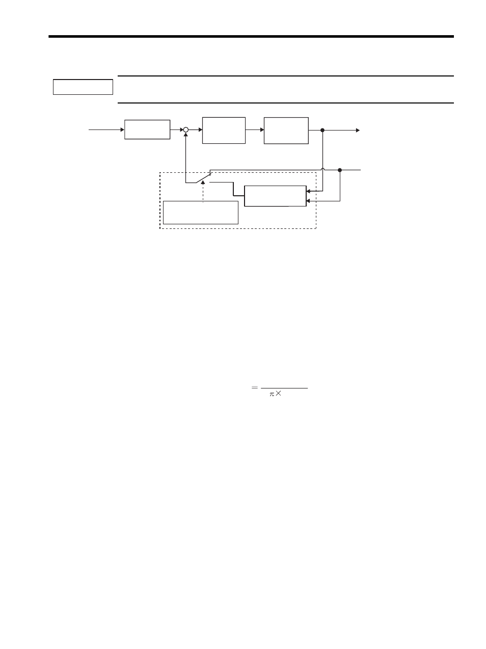
Speed loop
PI control
Speed
reference
Error counter
output
Position loop gain
(Pn100,Pn101)
(Pn111)
(Pn102)
+
-
Torque reference
low-pass filter
(Pn401)
Speed feedback
compensation
Speed feedback
Torque reference
Speed feedback compensation function
Selection of speed feedback
compensation function
(Pn110.1)
Speed loop integral time constant (Pn101)
4000
2
Pn100