3) 800 w, single-phase 200v, Important – Yaskawa SGDS Sigma III Servo Amplifier User Manual
Page 108
5.1 Wiring Main Circuit
5-5
Designing a Power ON Sequence
Note the following points when designing the power ON sequence.
• Design the power ON sequence so that main power is turned OFF when a servo alarm signal is output.
(See the circuit figure above.)
• Hold the power ON button for at least two seconds just after the control power is turned ON. The
SERVOPACK will output a servo alarm signal for two seconds or less when power is turned ON. This is
required in order to initialize the SERVOPACK.
• Select the power supply specifications for the parts in accordance with the input power supply.
Power Supply Harmonic Waves
If a countermeasure against power supply harmonic waves is needed for other requirements, insert the AC
reactor to AC power supply input of the SERVOPACK or insert the DC reactor to the internal DC main
circuit.
Refer to 5.6.5 AC/DC Reactor for Harmonic Suppression.
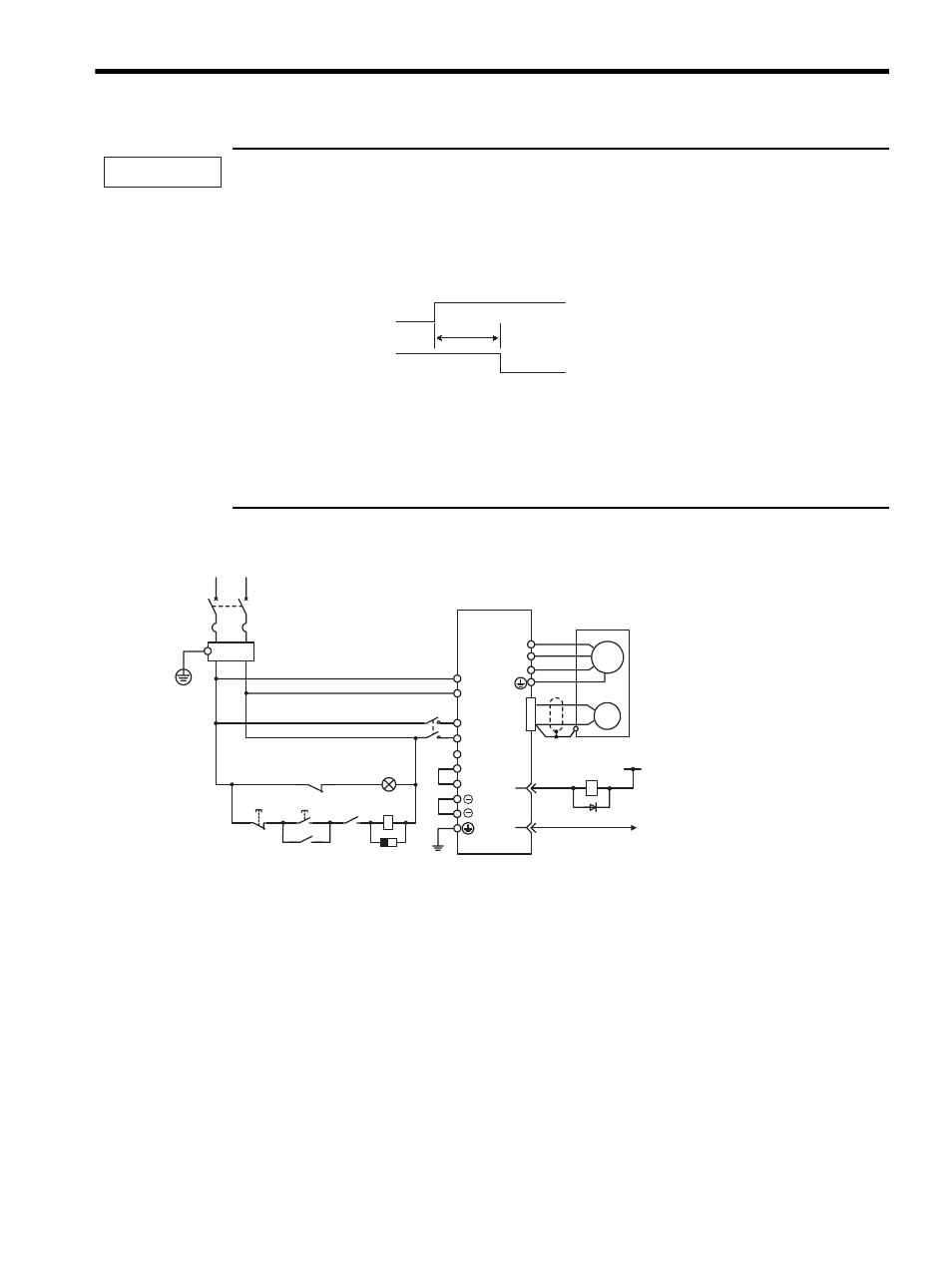
(3) 800 W, Single-phase 200V
Note: L3 terminal is not used for the single-phase 200 V, 800 W SERVOPACKs. Do not connect.
IMPORTANT
Power supply
Servo alarm (ALM)
output signal
2.0 s max.
L1
L1C
PG
SERVOPACK
SGDS-08A12A
U
V
W
M
ALM-
0 V
24
1Ry
ALM+
31
32
1D
OFF
1KM
1Ry
ON
(For servo alarm
display)
1KM
1PRT
1Ry
1KM
L3
L2
L2C
Main
power supply
Main power
supply
CN1
1QF
R
T
1PL
FIL
+24V
A
B
C
D
: Indicator lamp
: Surge protector
: Flywheel diode
1PL
1PRT
1D
1QF
FIL
1KM
1Ry
: Molded-case circuit breaker
: Noise filter
: Magnetic contactor
: Relay
B2
B3
1
2