3 position loop gain, 3 position loop gain -21 – Yaskawa SGDS Sigma III Servo Amplifier User Manual
Page 248
8.5 Manual Tuning
8-21
• Servo Gain Manual Tuning
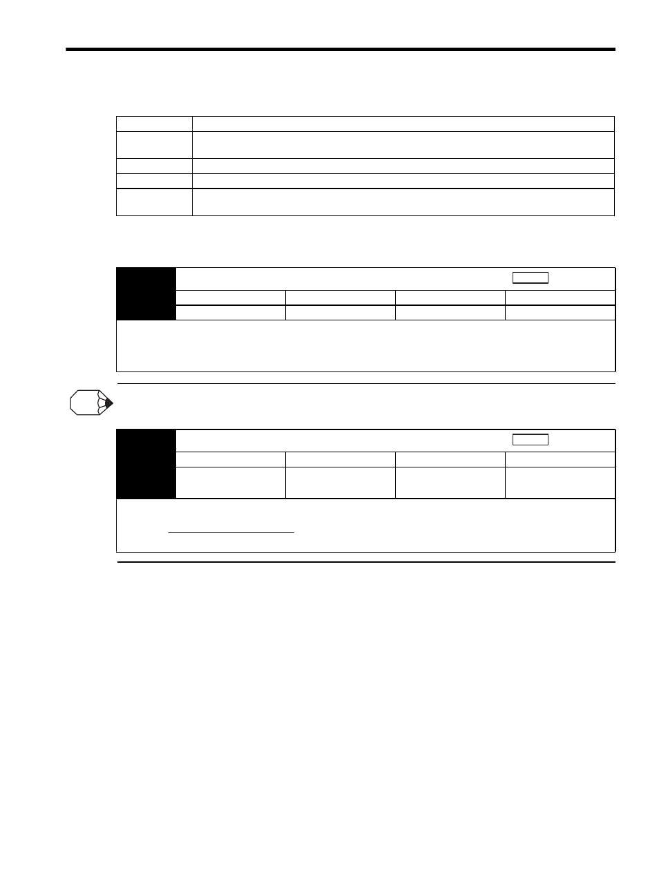
8.5.3 Position Loop Gain
If the position loop gain (Pn102) can not be set high in the mechanical system, an overflow alarm may occur during high
speed operation. In this case, increase the values in the following parameter to suppress detection of the overflow alarm.
Step
Explanation
1
Increase the speed loop gain (Pn100) to within the range so that the machine does not vibrate. At the
same time, decrease the speed loop integral time constant (Pn101).
2
Adjust the 1st Step 1st torque reference filter time constant (Pn401) so that no vibration occurs.
3
Repeat the steps 1 and 2. Then reduce the value for 10 to 20%.
4
For the position control, increase the position loop gain (Pn102) to within the range so that the machine
does not vibrate.
Pn102
Position Loop Gain (Kp)
Setting Range
Setting Unit
Factory Setting
Setting Validation
1.0 to 2,000.0/s
0.1/s
40.0/s
Immediately
The responsiveness of the position loop in the SERVOPACK is determined by the position loop gain. The responsiveness
increases and the positioning time decreases when the position loop gain is set to a higher value. In general, the position
loop gain cannot be set higher than natural vibrating frequency of the mechanical system, so the mechanical system must be
made more rigid to increase its natural vibrating frequency and allow the position loop gain to be set to a high value.
Position
INFO
Pn520
Excessive Position Error Alarm Level
Setting Range
Setting Unit
Factory Setting
Setting Validation
1 to 1,073,741,823
(2
30
-1) reference units
Reference units
262,144 reference unit
Immediately
This parameter’s new setting must satisfy the following condition.
Position
Pn520
Pn102
2.0
≥
Max. feed speed (reference units/s) ×