5) terminal processing, 15 (5) terminal processing, 4 wiring mechatrolink ii communications – Yaskawa SGDS Sigma III Servo Amplifier User Manual
Page 118: Host controller l1 ln l2 terminator
5.4 Wiring MECHATROLINK II Communications
5-15
(5) Terminal Processing
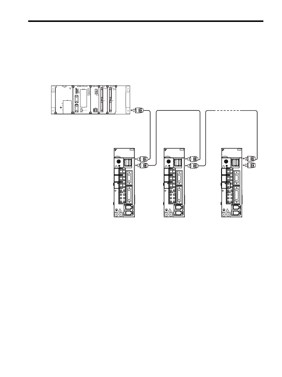
Install a Terminator on the last SERVOPACK and host controller.
For more information on Terminators, refer to 4.4.10 MECHATROLINK/MECHATROLINK II Communication
Cable, 4.4.11 MECHATROLINK/MECHATROLINK II Terminator.
A MECHATROLINK II wiring diagram is shown below.
Note: 1. The total cable length must be L1 + L2 ... + Ln
≤ 50.
2. The length of the cable stations (L1, L2 ... Ln) must be 0.5 m or more.
O
N
OF
F
Host controller
L1
Ln
L2
Terminator
YASKAWA SERVOPACK 2 0 0 V
S G D S - 0 2 A 1 2 A
SW1
CHARGE
L1
L2
L1C
L2C
B1/
B2
U
V
W
C
N
6
C
N
3
C
N
1
C
N
2
C
N
4
A / B
YASKAWA SERVOPACK 2 0 0 V
S G D S - 0 2 A 1 2 A
SW1
CHARGE
L1
L2
L1C
L2C
B1/
B2
U
V
W
C
N
6
C
N
3
C
N
1
C
N
2
C
N
4
A / B
YASKAWA SERVOPACK 2 0 0 V
S G D S - 0 2 A 1 2 A
SW1
CHARGE
L1
L2
L1C
L2C
B1/
B2
U
V
W
C
N
6
C
N
3
C
N
1
C
N
2
C
N
4
A / B