Yaskawa MEMOCON GL120 User Manual
Page 123
4.3 CPU Modules
— 4-67 —
4) MEMOBUS network communications specifications are shown in the following table.
Table 4.17 MEMOBUS Network Communications Specifications
Item
Specifications
Communications
Method
Half-duplex, stop-start synchronization
Transmission
Levels
Conform to RS-232C.
Protocol
MEMOBUS Protocol
Baud Rate
19,200/9,600/7,200/4,800/3,600/2,400/2,000/1,800/1,200/600/300/150 bps
Communications
Mode
RTU mode or ASCII mode
Data Format
The following data format is used between the master and slaves, between
the master and modems, and between the modems and slaves:
1) Data bit length: 8 (RTU mode) or 7 (ASCII mode) bits
2) Parity check:
Yes/No
3) Parity:
Odd or even
4) Stop bits:
1 or 2
Transmission
Distance
15 m (Can be extended to 4.5 km maximum by using Yaskawa modem.)
Transmission Error
Detection
CRC-16 (RTU Mode), LRC (ASCII Mode)
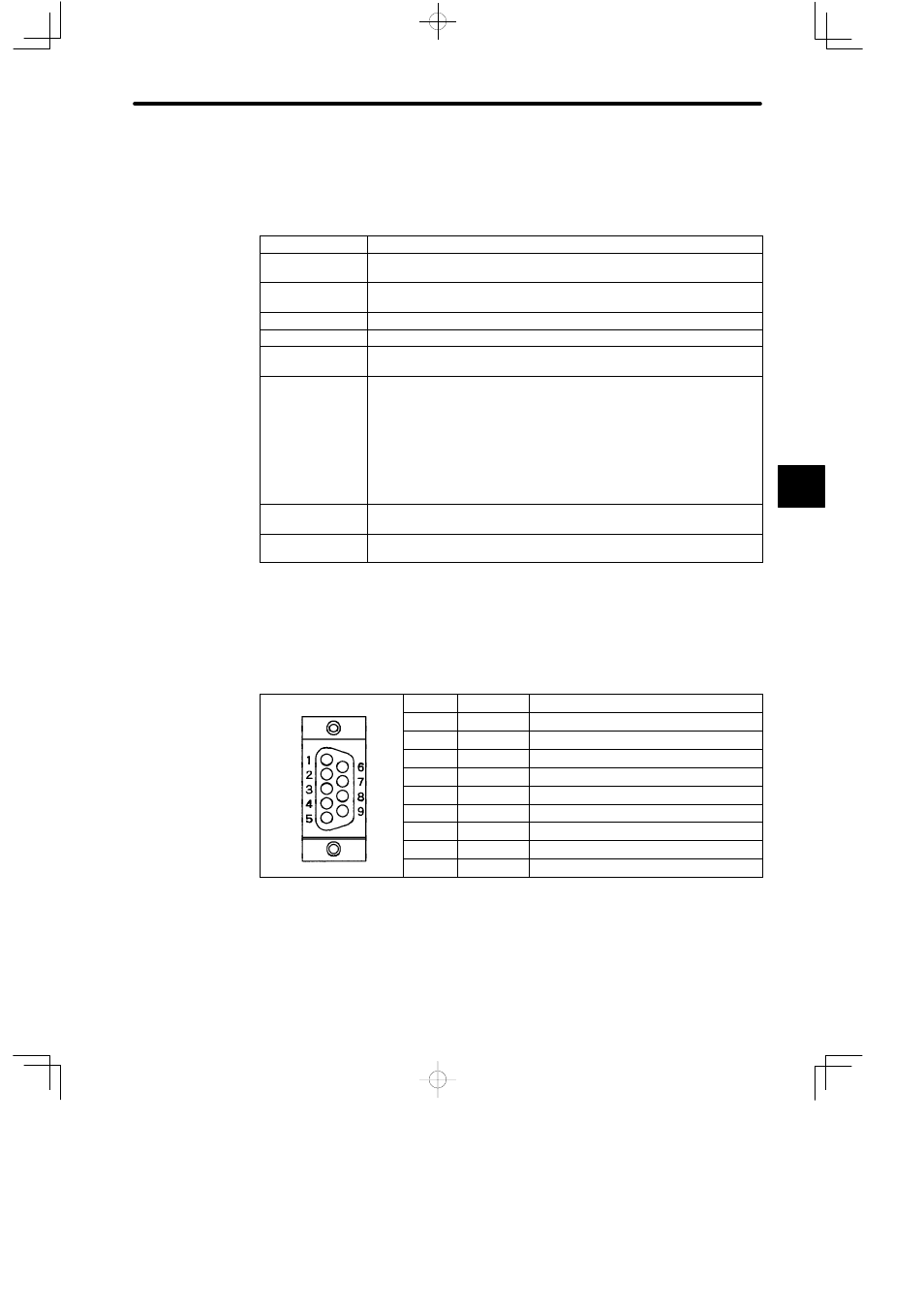
5) D-sub connector (9-pin, female) is used to connect MEMOBUS port. The connector pin
arrangements and the signal names are shown below:
Table 4.18 Pin Arrangement and Names of Signals
Pin No.
Symbol
Signal Name
1
FG
Frame ground
2
TXD
Transmission data
3
RXD
Reception data
4
RTS
Request to sent
5
CTS
Clear to send
6
DSR
Data set ready
7
GND
Signal ground
8
EST
Element status
9
DTR
Data terminal ready
6) COM Instructions (COMM, COMR)
Note
(1) The MEMOBUS port of CPU Module does not support the COM instructions (COMM,
COMR).
4