Yaskawa MEMOCON GL120 User Manual
Page 262
System Components: Functions and Specifications
4.4.13 Ethernet Interface Module cont.
— 4-206 —
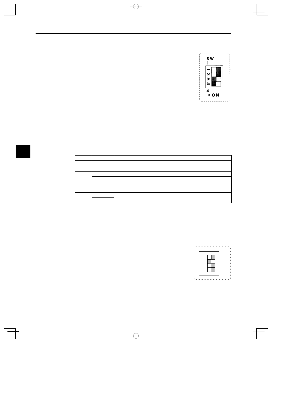
6) DIP Switch
a) The DIP switch is composed of 4 pins. The pins are num-
bered from 1 to 4 as shown in the diagram at the right.
b) Each pin is turned ON when pressed to the right.
c) The setting of each pin is effective (read) at the following
times:
(1) When the reset switch is pressed.
(2) When the power is turned ON to the Power Supply Module of the CPU Rack.
d) Each pin’s function is shown in the following table.
Table 4.86 Function of DIP Switch
Pin
Settings
Function
1
ON
Sets Module to Self-diagnosis mode. (Not normally used.)
OFF
Sets Module to RUN mode.
2
ON
Selects the 10Base5 port.
OFF
Selects the 10Base-T port.
3
ON
For future use. (Leave set to OFF.)
OFF
(
)
4
ON
For future use. (Leave set to OFF.)
OFF
(
)
Note
The 10Base5 port and 10Base-T port cannot be used at the same time. Using the ports at the
same time may damage the Ethernet Interface Module or cause malfunctions.
e) Examples of setting the DIP switch are shown below:
Example 1
When the DIP switch is set as shown in the diagram on the right,
the Ethernet Interface Module is set as follows:
• RUN mode
• 10Base5
4
A
EXAMPLE
"
1234
1
4
SW
ON