Yaskawa MEMOCON GL120 User Manual
Page 62
Advertising
System Components: Functions and Specifications
4.2.1 Appearance of Power Supply Modules cont.
— 4-6 —
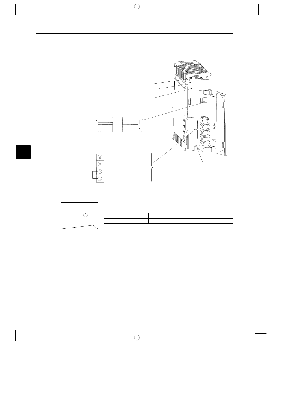
2. Appearance of PS05 (Model No. JRMSP-120CPS11100)
Jumper
Module Description (120CPS11100)
Color code (yellow)
LED area
Module mounting screw
(Use M4 Phillips screwdriver.)
Input voltage
selector switch
Field wiring terminals (use M3 Phillips screwdriver)
ACG: Filter ground terminal
FG: Protective ground terminal
* M4 Phillips screws are used for terminals.
or
AC1: Field wiring terminal 1
AC2: Field wiring terminal 2
Input voltage range
85 to 132 VAC
Input voltage range
170 to 264 VAC
LED
Color
Indication when ON
POWER
Green
Power Supply Module is operating normally.
Figure 4.3 Appearance with Cover Open
4
POWER
120 CPS 111 00
LED area
Advertising
This manual is related to the following products: