Yaskawa MEMOCON GL120 User Manual
Page 211
4.4 Communications Modules
— 4-155 —
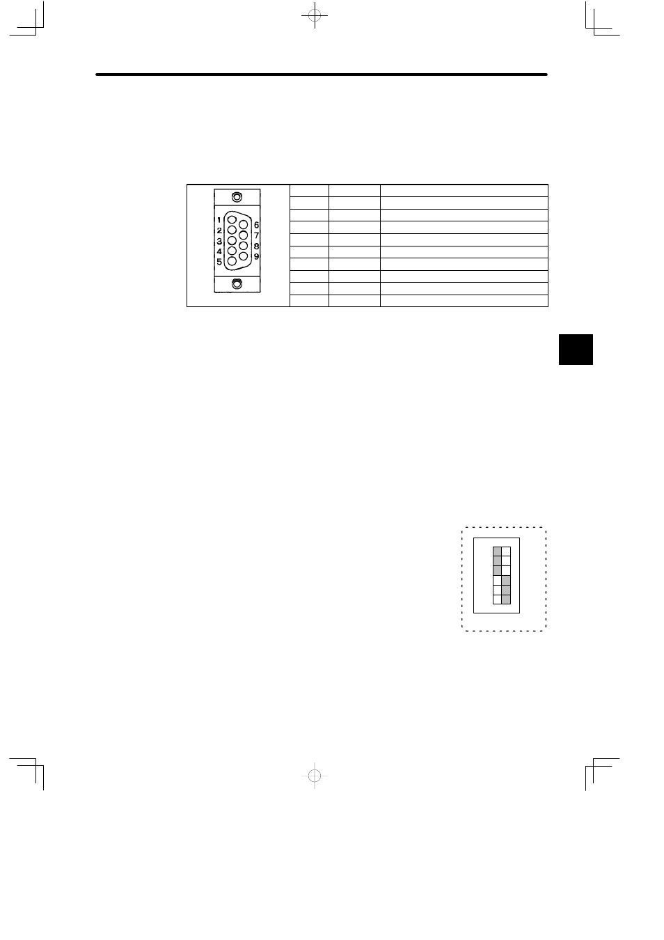
e) A D-sub connector (9-pin, female) is used to connect the MEMOBUS port. The con-
nector pin arrangements and the signal names are shown in the following table
Table 4.64 Pin Arrangement and Signal Names of MEMOBUS Port
Pin No.
Symbol
Signal Name
1
FG
Protective ground
2
TXD
Transmission data
3
RXD
Reception data
4
RTS
Request to send
5
CTS
Clear to send
6
DSR
Data set ready
7
GND
Signal ground
8
−
Not used.
9
DTR
Data terminal ready
f) COM Instructions (COMM, COMR)
Note
(1) COM Instructions (COMM, COMR) cannot be used for the MEMOBUS port of a PC
Link Module.
(2) The COMM instruction can be used for the MEMOBUS port of the following two com-
munications Modules.
MEMOBUS Module (RS-232): Model JAMSC-120NOM26100
MEMOBUS Module (RS-422): Model JAMSC-120NOM27100
(3) The COMR instruction can be used only for the MEMOBUS ports of the Remote I/O
Receiver Module.
5) DIP Switch
a) DIP switch is composed of 6 pins. The pins are numbered
from 1 to 6 as shown in the diagram at the right.
b) Each pin is turned ON when pressed to the right.
c) The setting of each pin is effective (read) at the following
times:
(1) When the reset switch is pressed.
(2) When the power is turned ON to the Power Supply Module of the CPU Rack.
4
123456
1
6
SW
ON