Yaskawa MEMOCON GL120 User Manual
Page 140
System Components: Functions and Specifications
4.3.5 Using CPU Modules 2 (For CPU21) cont.
— 4-84 —
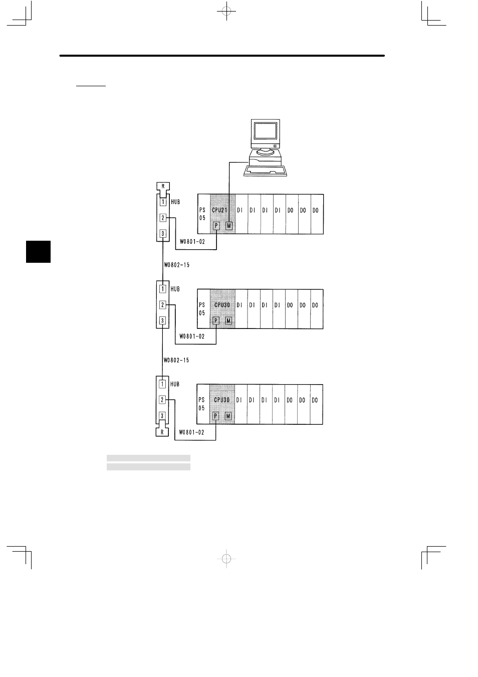
c) An example using bridge mode is shown below:
(1) System Configuration
PS05:
Power Supply Module (3 A)
CPU21:
CPU Module (16 KW)
CPU30:
CPU Module (32 KW)
DI:
12/24 VDC 16-point Input Module
DO:
12/24 VDC 16-point Output Module
MB10:
10-slot Mounting Base
HUB:
MEMOBUS PLUS Hub Module
R:
MEMOBUS PLUS Terminator
W0801-02:MEMOBUS PLUS Branch Line Cable (2.0 m)
W0802-15:MEMOBUS PLUS Trunk Line Cable (15.0 m)
M:
MEMOBUS Port
P:
MEMOBUS PLUS Port
Personal computer
(with RS-232C Interface)
MEMOBUS
communications
Rack 1
(CPU Rack)
MB10
Rack 1
(CPU Rack)
MB10
Node address 2
Rack 1
(CPU Rack)
MB10
MEMOBUS
PLUS
Network
Node address 3
Node address 4
Connector 1 (CN1)
Connector 2 (CN2)
Connector 3 (CN3)
Figure 4.19 Using Bridge Mode
4
A
EXAMPLE
"