Yaskawa MEMOCON GL120 User Manual
Page 194
System Components: Functions and Specifications
4.4.6 MEMOBUS Modules (RS-422) cont.
— 4-138 —
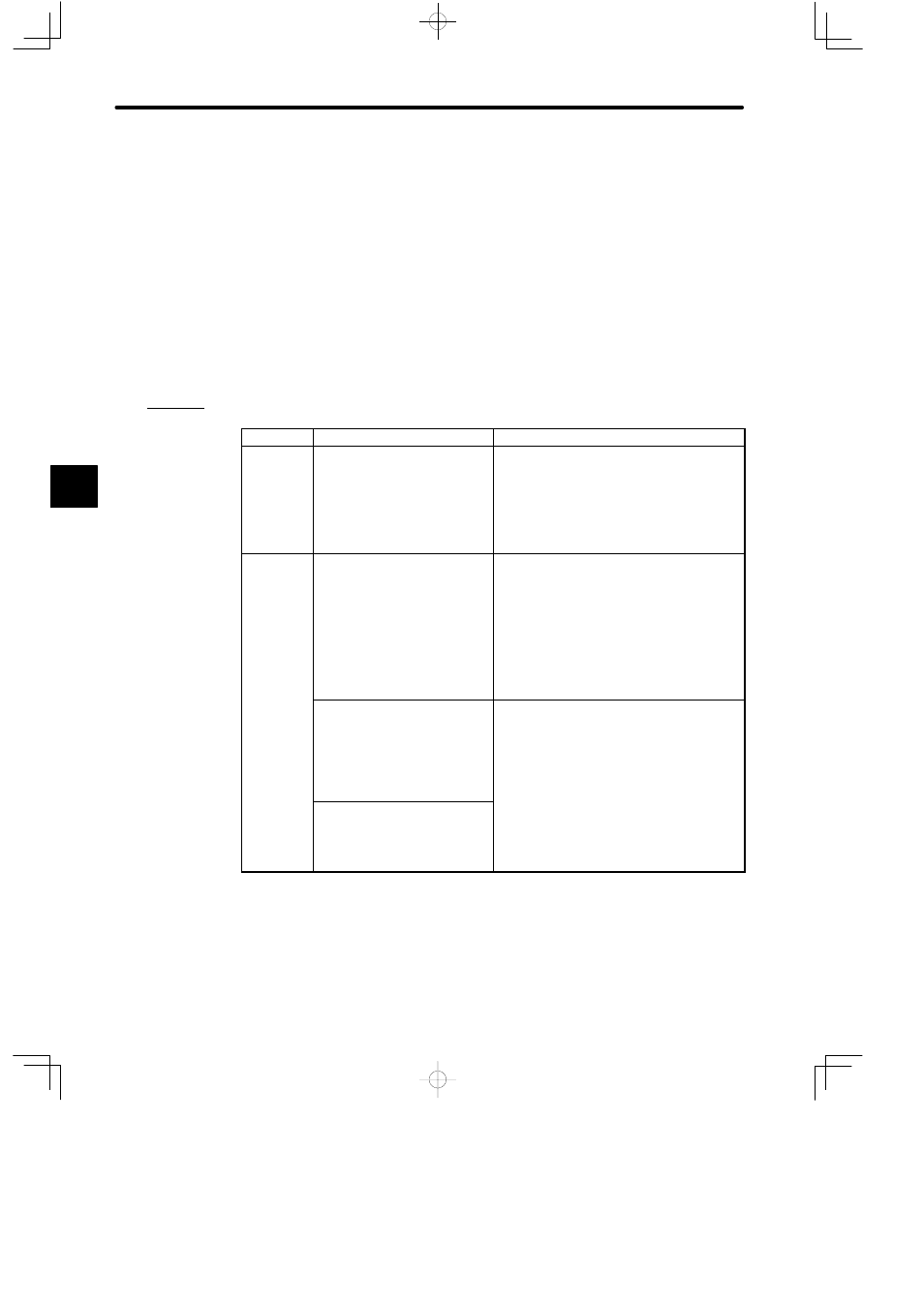
3) MEMOBUS Port
a) Devices connectable to the MEMOBUS ports are shown in the following table. Each
of these devices must be equipped with an RS-422 interface. In addition, depending
on the type of device, the MEMOBUS port settings will need to be altered. This set-
tings are altered using the DIP switch on the front of the Module. Refer to 4) DIP
Switch later in this section.
b) Refer to Table 4.58 on page 4-137 for details on MEMOBUS port specifications.
c) Examples of how to use the MEMOBUS Module are shown in Figure 4.33 to Figure
4.36.
Table 4.59 Example of Devices connectable to MEMOBUS Port
Type
Devices
Remarks
Master
Yaskawa ACGC4000-series FA
Monitors
D
Set MEMOBUS port to slave port.
D
Creation of communications program not
needed.
D
Communications performed using
MEMOBUS protocol
Slaves
Yaskawa Inverters
1) VS-616G3 plus
2) VS-606PC3
3) VS-mini C
Note Use Inverters which sup-
port MEMOBUS protocol.
D
Set MEMOBUS port to combined
master/slave port.
D
Create communications program using
COMM instructions in the GL120/GL130.
D
Use MEMOBUS protocol for communications
protocol.
Yaskawa Servo Amplifiers
1) SGD-jjH
2) CACR-HRjjBAB
3) CACR-HRjjBB
D
Set MEMOBUS port to combined
master/slave port.
D
Set MEMOBUS port to transparent mode.
D
Create communications program using
COMM instructions in the GL120/GL130.
ASCII devices
1) Bar code readers
2) Electronic scales
COMM instructions in the GL120/GL130.
D
Use slave protocol for communications
protocol.
4
A
EXAMPLE
"