Yaskawa MEMOCON GL120 User Manual
Page 27
2.1
Overview of the MEMOCON GL120 and GL130
— 2-3 —
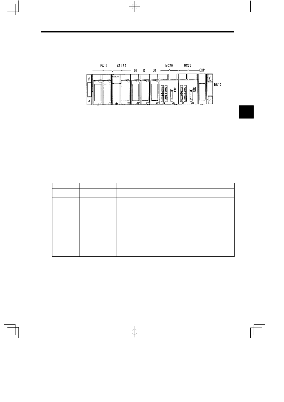
Example 2
Example of system configuration for MEMOCON GL130
PS10:
Power Supply Module
(7 A)
DI:
Digital Input Module
EXP:
Expander Module
CPU20: CPU Module (16 KW)
DO:
Digital Output Module
MB12: 12-slot Mounting Base
CPU30: CPU Module (32 KW)
MC20: Four-axis Motion Module
4) The following table shows the main Modules and other devices used in the GL120 and
GL130. Any items listed as “Optional” in the Use column may be used as required accord-
ing to the system control specifications of the GL120 or GL130.
Table 2.1 Main GL120 and GL130 Modules and other Products
Use
Name
Features
Required
Power Supply
Module
Supplies DC power to various Modules to operate them.
Required
CPU Module
1) Stores the user program, solves the program based on the information
from the input section, and outputs the results to the output section.
There are 5 types of CPU Modules, namely the CPU10, CPU20,
CPU21, CPU30, and CPU35.
2) Equipped with 1 MEMOBUS port (slave, RS-232C).
(CPU20, CPU21, CPU30, CPU35)
3) Equipped with 1 MEMOBUS PLUS port
(CPU20, CPU21, CPU30, CPU35)
4) Execute the ROM operation.
(CPU10, CPU21)
2