Yaskawa MEMOCON GL120 User Manual
Page 148
IMPORTANT
System Components: Functions and Specifications
4.3.6 Using CPU Modules 3 (For CPU10) cont.
— 4-92 —
4) The following table shows the communications specifications of the MEMOBUS net-
work.
Table 4.33 MEMOBUS Network Communications Specifications
Item
Specifications
Communications Mode
Half-duplex, start-stop synchronization
Transmission Levels
Conforms to RS-232C
Protocol
MEMOBUS protocol
Baud Rate
19,200/9,600/7,200/4,800/3,600/2,400/2,000/1,800/1,200/
600/300/150 bps
Communications Mode
RTU mode or ASCII mode
Data Format
The following data format is used between master and
slaves, between master and modems, and between
modems and slaves:
1)
Data bit length: 8 (RTU mode) or 7 (ASCII mode)
2)
Parity check: Yes or no
3)
Parity: Odd or even
4)
Stop bits: 1 or 2
Transmission Distance
15 m (Can be extended to 4.5 km maximum by using a
Yaskawa modem)
Transmission Error Detection
CRC-16 (RTU mode) or
LRC (ASCII mode)
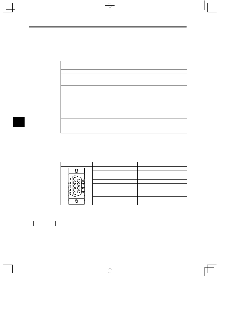
5) D-sub connectors (9-pin, female) are used to connect the MEMOBUS ports. The connec-
tor pin arrangements and the signal names are shown below.
Table 4.34 Pin Arrangement and Names of Signals for MEMOBUS Ports
Pin No.
Symbol
Signal Name
1
FG
Frame ground
2
TXD
Transmission data
3
RXD
Reception data
4
RTS
Request to send
5
CTS
Clear to send
6
DSR
Data set ready
7
GND
Signal ground
8
EST
Element status
9
DTR
Data terminal ready
6) COM Instructions (COMM, COMR)
(1) The COM instructions (COMM and COMR) cannot be used for MEMOBUS port 1 of the
CPU10 Module.
(2) The COMM instruction can be used for MEMOBUS port 2 of the CPU10 Module.
(3) The COMR instruction cannot be used for MEMOBUS port 2 of the CPU10 Module.
4