6 using cpu modules 3 (for cpu10), Installation location – Yaskawa MEMOCON GL120 User Manual
Page 144
System Components: Functions and Specifications
4.3.6 Using CPU Modules 3 (For CPU10)
— 4-88 —
4.3.6 Using CPU Modules 3 (For CPU10)
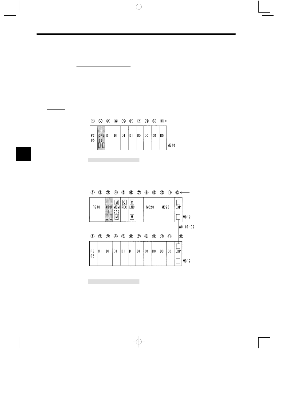
1. Installation Location
1) The CPU10 Module can be mounted to any slot on the Mounting Base of Rack 1. It will
occupy 1 slot of the Rack.
2) The CPU10 Module is normally mounted to the slot on the left next to the Power Supply
Module on Rack 1, as is shown in the following two examples.
a) Mounting the CPU10 with One Rack
Slot No.
Rack 1 (CPU Rack)
PS05:
Power Supply Module (3 A)
CPU10:
CPU10 Module (8 KW)
MB10:
10-slot Mounting Base
DI:
12/24 VDC 16-point Input Module
DO:
12/24 VDC 16-point Output Module
b) Mounting the CPU10 with Two Racks
Slot No.
Rack 2
Rack 1 (CPU Rack)
PS10:
Power Supply Module (7 A)
PS05:
Power Supply Module (3 A)
CPU10:
CPU10 Module (8 KW)
MEM232: RS-232 MEMOBUS Module
RDC:
Remote I/O Driver Module
LNC:
PC Link Module
DI:
12/24 VDC 16-point Input Module
DO:
12/24 VDC 16-point Output Module
MC20:
4-axis Motion Module
EXP:
Expander Module
MB12:
12-slot Mounting Base
W0100-02:Rack-to-rack I/O Cable (0.2 m)
Figure 4.20 Example of Mounting CPU10 Modules
4
A
EXAMPLE
"