Yaskawa MEMOCON GL120 User Manual
Page 429
Installation and Wiring
5.3.5 Grounding cont.
— 5-72 —
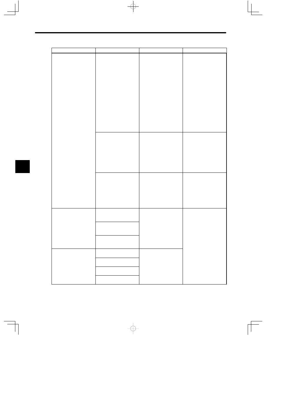
Product
Related Manuals
Grounding Methods
Name
Communications Modules MEMOBUS Module
(RS-422)
1) Connect the shield of
the cable connecting
the Module to an
external device to the
signal ground (PGND)
pin of the
communications port
of the Module.
2) If the communications
port of the external
device is equipped
with a signal ground
pin, connect this to the
signal ground (SGND)
pin of the
communication port of
the Module.
COM Instructions
User’s Manual
(SIEZ-C825-70.14)
M-NET Module
1) Ground the FG
terminal of the
Module.
2) Connect the shield of
the transmission cable
to the ground terminal
of the Module at one
point.
M-NET Module
User’s Manual
(SIEZ-C825-70.12)
YENET 1600-D Module
1) Connect the shield of
the transmission cable
to the ground terminal
of the
Communications
Power Supply at one
point, and to the
network at one point.
YENET 1600-D Module
User’s Manual
(SIE-C825-70.20)
Analog Input Modules
Analog Input Module
(±10 V, 4 channels)
1) Ground the FG
terminal of the
Module.
120-series I/O Modules
User’s Manual
(SIEZ-C825-20.22)
Analog Input Module
(0 to 10 V, 4 channels)
od e
2) Connect the shield of
analog signal input
Analog Input Module
(4 to 20 mA, 4 channels)
analog signal input
cable to the shield
terminal of the
Module.
Analog Output Modules
Analog Output Module
(±10 V, 2 channels)
Ground the shield of
analog signal output cable
th
t
l d i
Analog Output Module
(0 to 10 V, 2 channels)
g g
p
on the external device
end.
Analog Output Module
(0 to 5 V, 2 channels)
Analog Output Module
(4 to 20 mA, 2 channels)
5