Yaskawa MEMOCON GL120 User Manual
Page 338
System Components: Functions and Specifications
4.8.1 Expander Module cont.
— 4-282 —
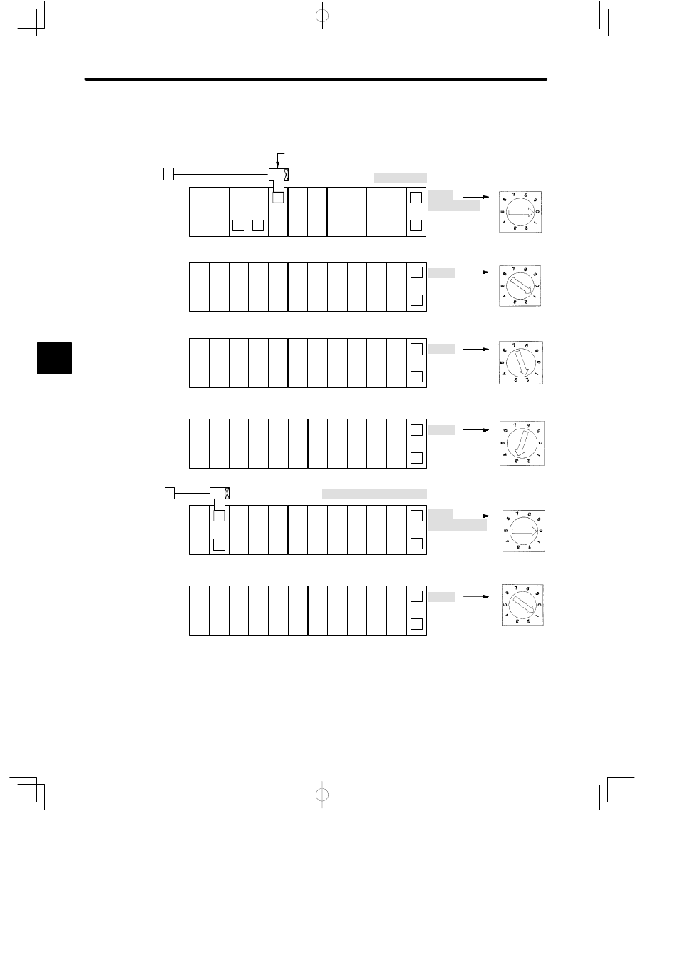
Example
Rack No. Setting Example
Local channel
EXP
RRC
PS
05
Rack 1
(Receiver Rack)
DI
DI
DI
DI
DI
DI
DI
DI
DI
MB12
EXP
DI
PS
05
W0100-02
Rack 2
MB12
DI
DI
DO DO DO DO DO DO DO
Setting the rotary
switch on Expander
Module
EXP
DI
PS
05
EXP
CPU30
PS10
M
P
W0100-02
MC20
MC20
Rack 2
Rack 1
(CPU Rack)
DI
DI
DI
DI
DI
DI
DI
DI
DI
RDC DI
DO
MB12
MB12
EXP
DI
PS
05
W0100-02
Rack 3
DI
DI
DI
DI
DI
DI
DI
DI
DI
MB12
EXP
DO
PS
05
W0100-02
Rack 4
MB12
DO DO DO DO DO DO DO DO DO
T-adapter
R (Terminator)
A
Conversion
Adapter
Branch line coaxial cable*1
T
C
A
T
C
R
Main line
coaxial cable
Remote channel 1 /Station 1
PS10:
Power Supply Module (7A)
PS05:
Power Supply Module (3A)
CPU30:
CPU Module (32 KW)
RDC:
Remote I/O Driver Module
RRC:
Remote I/O Receiver Module
DI:
12/24 VDC 16-point Input Module
DO:
12/24-VDC 16-point Output Module
MC20:
4-axis Motion Module
EXP:
Expander Module
MB12:
12-slot Mounting Base
W0100-02:Rack-to-rack I/O Cable (0.2m)
M
Figure 4.86 Rack No. Setting Example
4