Yaskawa MEMOCON GL120 User Manual
Page 237
4.4 Communications Modules
— 4-181 —
Example 2
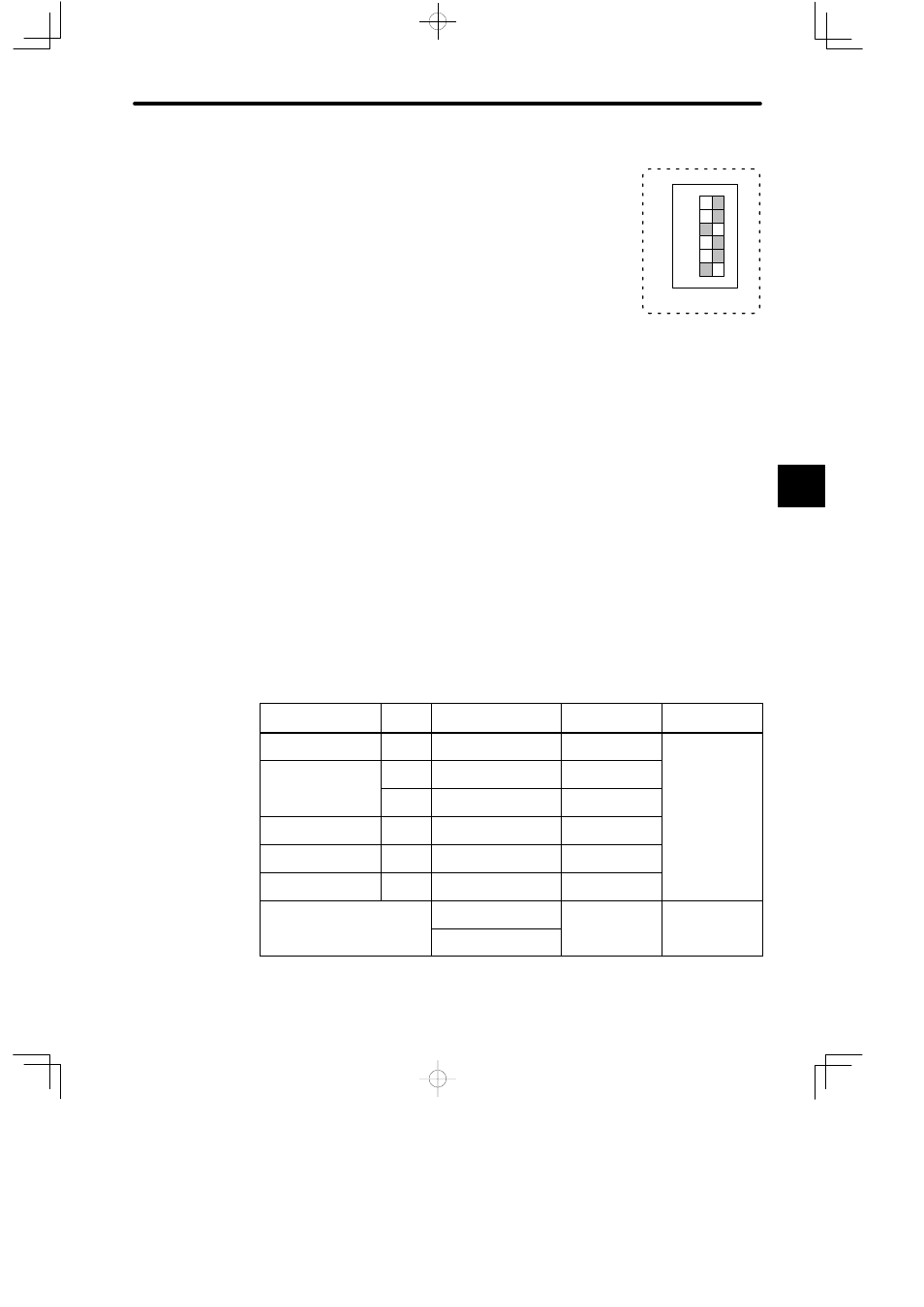
When the DIP switch is set as shown in the diagram on the right,
the Distributed I/O Driver Module is set as follows:
• Internal terminator is not connected.
• Normal RUN mode
• Hold mode
• 4 Mbps
6) Reset Switch
a) Press the reset switch in the following cases:
(1) When you have changed the setting of the DIP switch.
(2) When errors have occurred.
b) When the reset switch is pressed, communications between the Distributed I/O Driver
Module and other Distributed I/O Slave Modules are interrupted. Communications re-
start when the switch is released.
7) CPU Module Versions
The CPU Module and MEMOSOFT versions that are required to use a 2000-Series Re-
mote I/O Driver Module are shown in the following table.
Table 4.75 Versions Supporting the Distributed I/O Driver Module
Name
Model
Name
Model No.
Version Number
Location of
Version Number
CPU Module (8 kW)
CPU10
DDSCR-120CPU14200 jj A01
onwards
Module
nameplate
CPU Module (16 kW) CPU20 DDSCR-120CPU34100 jj B05
onwards
a ep a e
CPU21
DDSCR-120CPU34110 jj A02
onwards
CPU Module (32 kW) CPU30
DDSCR-130CPU54100 jj B05
onwards
CPU Module (40 kW) CPU35
DDSCR-130CPU54110 jj A01
onwards
Remote I/O Receiver
Module
RIOR
COAX
JAMSC-120CRR13100 jj A09
onwards
MEMOSOFT
FMSGL-AT3 (for
English DOS)
1.40j onwards
In the middle at
the bottom of the
OSO
FMSGL-PP3E (for
P120 English version)
e bo o o
e
MEMOSOFT
startup screen.
Note
The nameplate is on the right side of the Module.
4
6
1
SW
ON
2
3
4
5
6
1