Yaskawa MEMOCON GL120 User Manual
Page 442
Advertising
Low Voltage Directives
6.1.2 Appearance of Power Supply Modules cont.
— 6-4 —
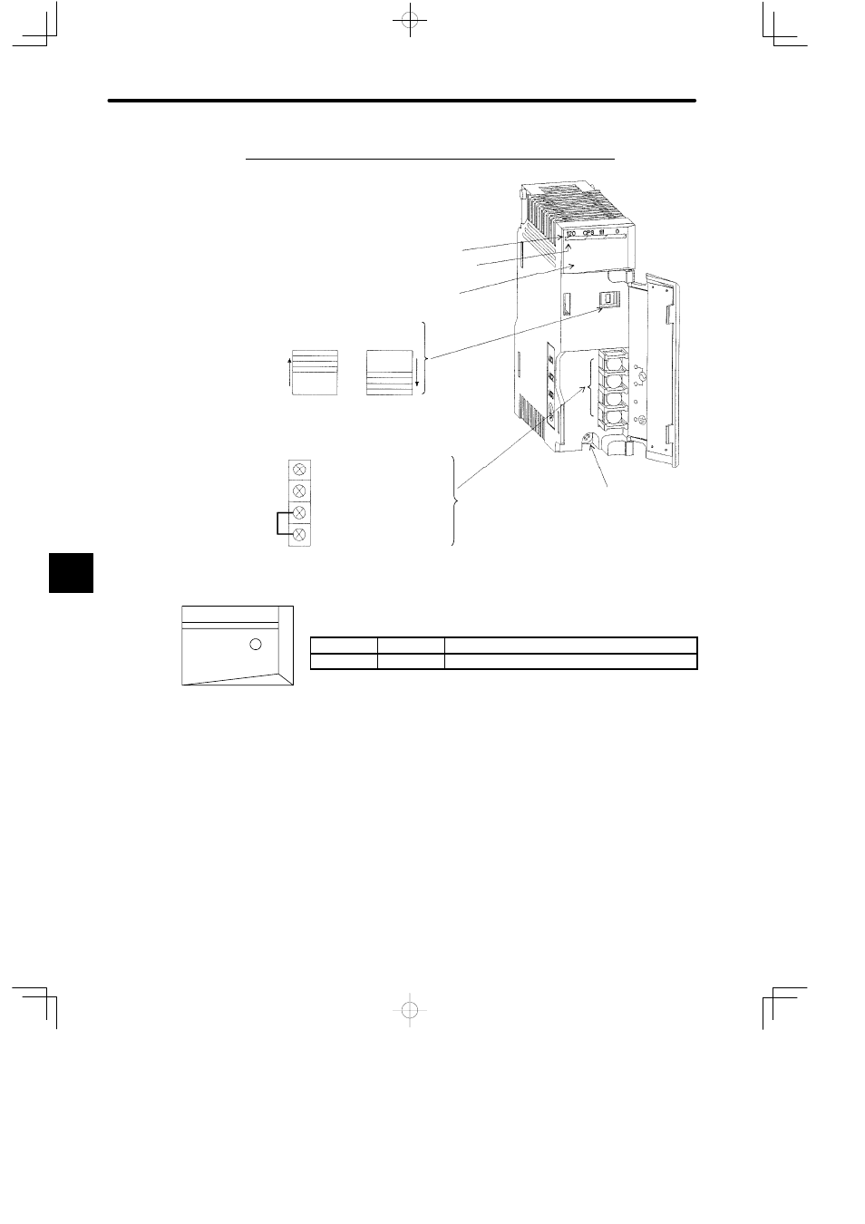
2. Appearance of PS05 (Model No. JRMSP-120CPS11109)
Jumper
Module Description (120CPS11109)
Color code (yellow)
LED area
Module mounting screw
(Use M4 Phillips screwdriver.)
Input voltage
selector switch
Field wiring terminals (use M3 Phillips screwdriver)
ACG: Filter ground terminal
FE: Functional earth terminal
* M4 Phillips screws are used for terminals.
or
AC1: Field wiring terminal 1
AC2: Field wiring terminal 2
Input voltage range
85 to 132 VAC
Input voltage range
170 to 264 VAC
9
LED
Color
Indication when ON
POWER
Green
Power Supply Module is operating normally.
Figure 6.3 Appearance with Cover Open
POWER
120 CPS 111 09
LED area
6
Advertising
This manual is related to the following products: