Yaskawa MEMOCON GL120 User Manual
Page 418
!
5.3 Panel Wiring
— 5-61 —
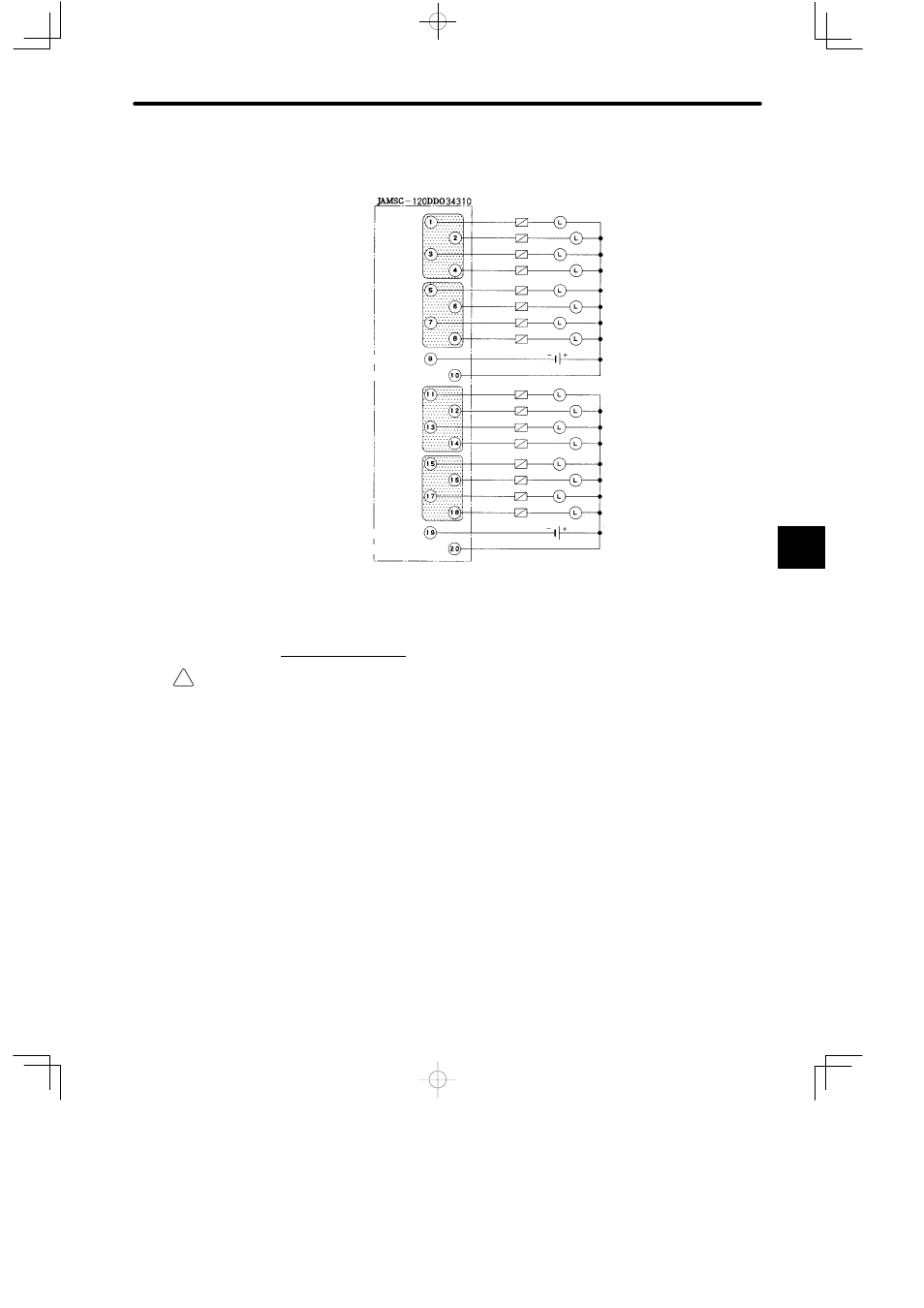
Example 2: Load Driving Power Supply for 12/24-VDC 16-point Output Module (sink)
Load driving
power supply
12/24 VDC
Fuse
Load
Output 1
Output 2
Output 3
Output 4
Output 5
Output 6
Output 7
Output 8
−Common 1
+Common 1
Output 9
Output 10
Output 11
Output 12
Output 13
Output 14
Output 15
Output 16
−Common 2
+Common 2
Fuse
Load
12/24 VDC
Figure 5.4 Load Driving Power Supply
2. I/O Signal Cables
Caution
Do not accidentally leave foreign matter such as wire chips on the Mounting Base or in the
Module when wiring. This may cause fires, failures, and malfunctions.
A. Digital I/O Modules with Terminal Blocks
1) There are 9 Digital I/O Modules with terminal blocks for external connections. (see Table
5.10.)
2) To connect to these Digital I/O Modules, use I/O signal cable of the size listed in Table
5.10. The cables differ in their permissible current capacity depending on the conditions
of use, such as the ambient operating temperature, so check the conditions of use and
select a cable of appropriate size.
5