Yaskawa MEMOCON GL120 User Manual
Page 213
4.4 Communications Modules
— 4-157 —
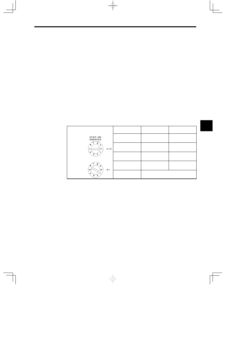
6) Rotary Switch
a) The rotary switch is used to set the station addresses of PC Link Modules.
b) There are two rotary switches. The top rotary switch is rotary switch 1 and the bottom
switch is rotary switch 2. Each switch has positions from 0 to 9.
c) The setting of the rotary switches is effective when the reset switch is pressed, or
when the power is turned ON to Power Supply Module of the Rack where the PC Link
Module is mounted.
d) The station address is set to between 1 and 32. The following table shows how to set
the station address.
e) The station address will be used as the slave address of the MEMOBUS port.
Table 4.66 Setting the Station Address
Example
Settings of Station Address 1
Station Address
Rotary Switch 1
Rotary Switch 2
1 to 9
0
1 to 9
Rotary switch 1
10 to 19
1
0 to 9
20 to 29
2
0 to 9
Rotary switch 2
30 to 32
3
0 to 2
Rotary switch 2
0 or 33 to 99
Not permitted.
Note
(1) Set the station address to between 1 and 32. If the address is set to 0 or, 33 to 99, nor-
mal communications will not be possible.
(2) Do not use the same address for more than one station within the same channel. If this
occurs, stations with the same address will not be able to communicate normally.
4