Yaskawa MEMOCON GL120 User Manual
Page 294
System Components: Functions and Specifications
4.6.2 High-speed Counter Module cont.
— 4-238 —
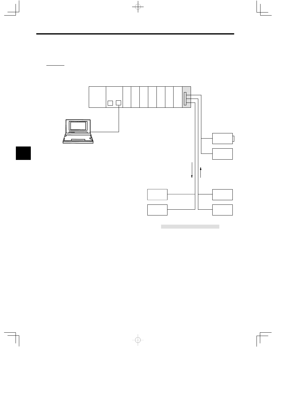
3) Example of System Configuration
The following diagram shows an example of a system configuration where a High-speed
Counter Module is applied to a high-speed pulse counting from a rotary encoder.
PS10:
Power Supply Module (7 A)
CPU30:
CPU Module (32 KW)
DI:
12/24-VDC 16-point Input Module
DO:
12/24-VDC 16-point Output Module
CTR:
High-speed Counter Module
MB12:
12-slot Mounting Base
W0203-03:MEMOBUS Cable (2.5 m)
DI
CTR
PS10
DI
DI
M
P
CPU30
DO DO
DO
DI
Local channel/Rack 1 (CPU Rack)
high-speed pulse:
AB-phase,1 −step
double-cycle, open
collector output,
12 VDC.
Rotary
encoder
D
External count
enable
D
External reset
P120C
Programming
Panel
DC power
supply
12 VDC
Limit switch
DC power
supply
24 VDC
Relay
DC power
supply
24VDC
D
Notch Output 0
D
Notch Output 1
D
Notch Output 2
D
Notch Output 3
MB12
W0203-03
M: MEMOBUS port
P: MEMOBUS PLUS port
Figure 4.71 Using High-speed Counter Modules
4) Related Manuals
Before operating the High-speed Counter Module, please read the following manual
carefully and be sure that you fully understand the information provided.
MEMOCON GL120, GL130 120-series High-speed Counter Module User’s Manual
(SIEZ-C825-20.24)
4
A
EXAMPLE
"