Yaskawa MEMOCON GL120 User Manual
Page 278
System Components: Functions and Specifications
4.5.2 Appearance of I/O Modules cont.
— 4-222 —
2. Appearance of I/O Modules with Connectors
1) Connectors are used to externally connect the following I/O Modules:
a) 12/24-VDC 32-point Input Module (JAMSC-120DDI35400)
b) 12/24-VDC 32-point Output Module (JAMSC-120DDO35410)
c) 12/24-VDC 64-point Input Module (JAMSC-120DDI36400)
d) 12/24-VDC 64-point Output Module (JAMSC-120DDO36410)
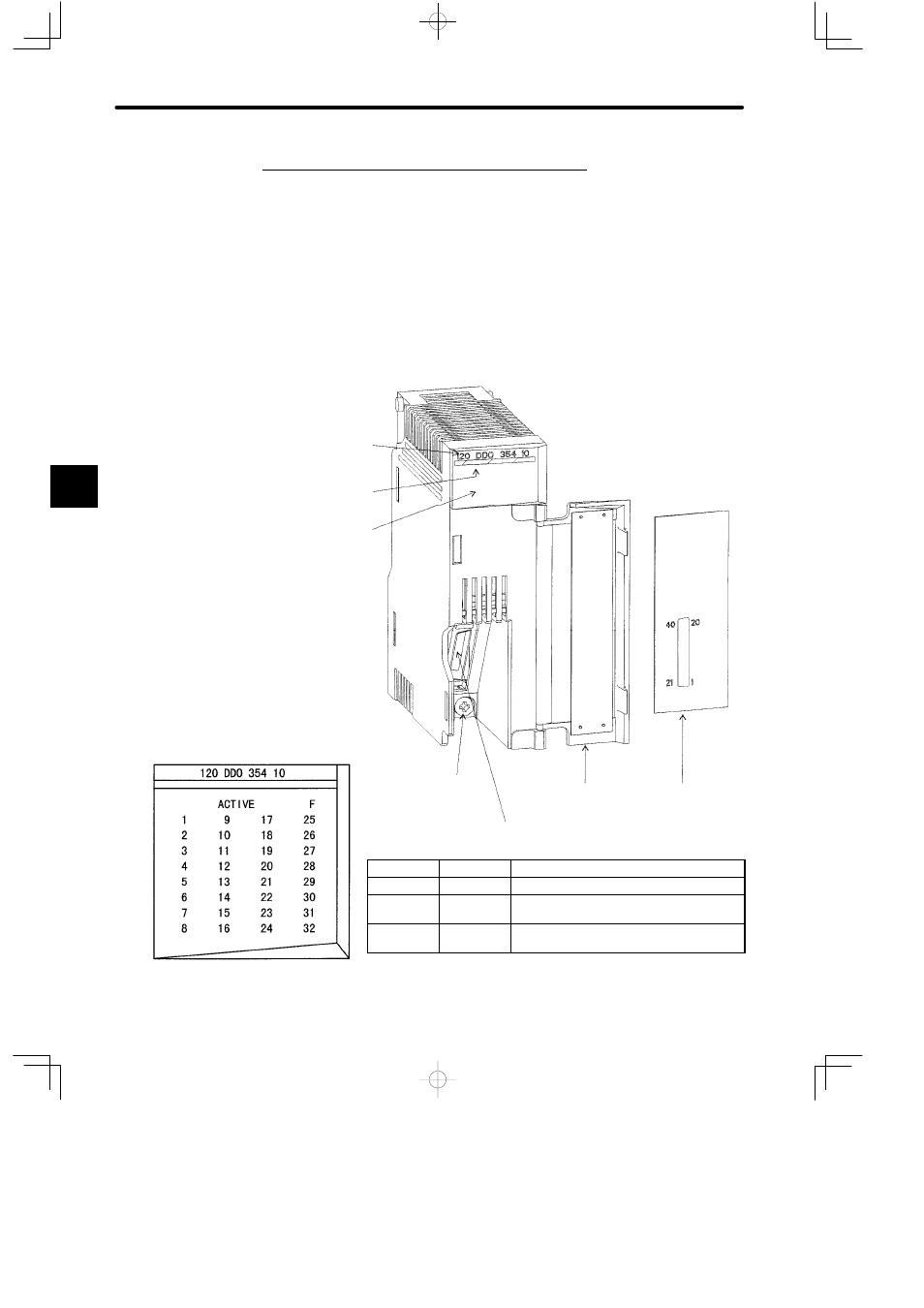
2) The following figure shows the appearance of a12/24-VDC, 32-point Output Module.
Color code
(dark blue)
Hinged cover
Signal label
insert
LED area
Module description
(120DDO35410)
32-point I/O Module connector
Module mounting screw
(Use M4 Phillips screwdriver.)
LED
Color
Indication when ON
ACTIVE
Green
Input/output processing
F
Red
Fuse broken, or external power supply not
connected.
1 to 32
Green
The corresponding LED is lit when the
output signal is ON.
Figure 4.66 Appearance of 12/24-VDC 32-point Output Module
4
LED area