Yaskawa MEMOCON GL120 User Manual
Page 124
System Components: Functions and Specifications
4.3.4 Using CPU Modules 1 (For CPU20, CPU30, and CPU35) cont.
— 4-68 —
(2) The COMM instruction can only be used for the MEMOBUS port of the following two
Communications Modules:
MEMOBUS Module (RS-232): Model JAMSC-120NOM26100
MEMOBUS Module (RS-422): Model JAMSC-120NOM27100
(3) The COMR instruction can only be used for the MEMOBUS port of the following Com-
munications Module:
Remote I/O Receiver Module: Model JAMSC-120CRR13100
3. MEMOBUS PLUS Port
1) Through the MEMOBUS PLUS port, the CPU Module runs high-speed communications
(baud rate: 1 Mbps) with other communications devices on a MEMOBUS network.
2) The following are some of the communications devices which can be connected to the
MEMOBUS port.
a) Programmable Controllers: MEMOCON GL120, GL130
b) Programming Panels: P120DN, P120MN, P120CN (with a SA85 Network Adapter)
c) Personal computers: IBM PC/AT or compatibles (with a SA85 Network Adapter)
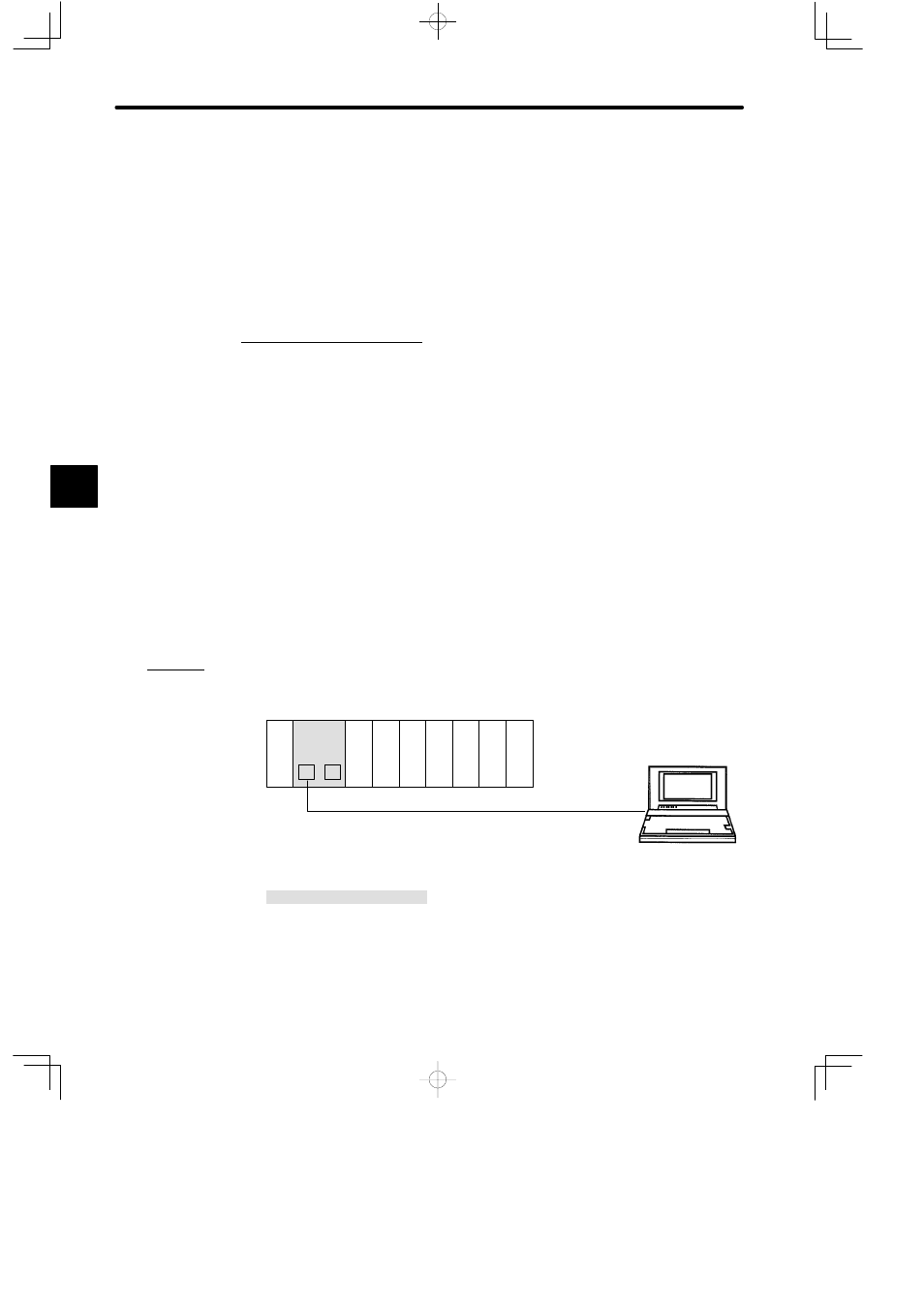
3) Examples of system configuration of MEMOBUS PLUS network are shown below:
Example 1
Connecting Programming Panel and GL120
M
P
DI
PS
05
Rack 1 (CPU Rack)
DI
DI
DI
DO DO DO
MB10
CPU20
PS05:
Power Supply Module (3 A)
CPU20:
CPU Module (16 KW)
DI:
12/24-VDC 16-point Input Module
DO:
12/24-VDC 16-point Output Module
MB10:
10-slot Mounting Base
W0800-03:MEMOBUS PLUS Cable (2.5 m)
M:
MEMOBUS Port
P:
MEMOBUS PLUS Port
W0800-03 cable
Node address 2
MEMOBUS PLUS communications (1 Mbps)
P120CN Programming Panel
(with a SA85 Network Adapter)
Node address 1
Figure 4.15 Connecting Programming Panel and GL120
4
A
EXAMPLE
"