2 installing modules – Yaskawa MEMOCON GL120 User Manual
Page 377
Installation and Wiring
5.2.2 Installing Modules
— 5-20 —
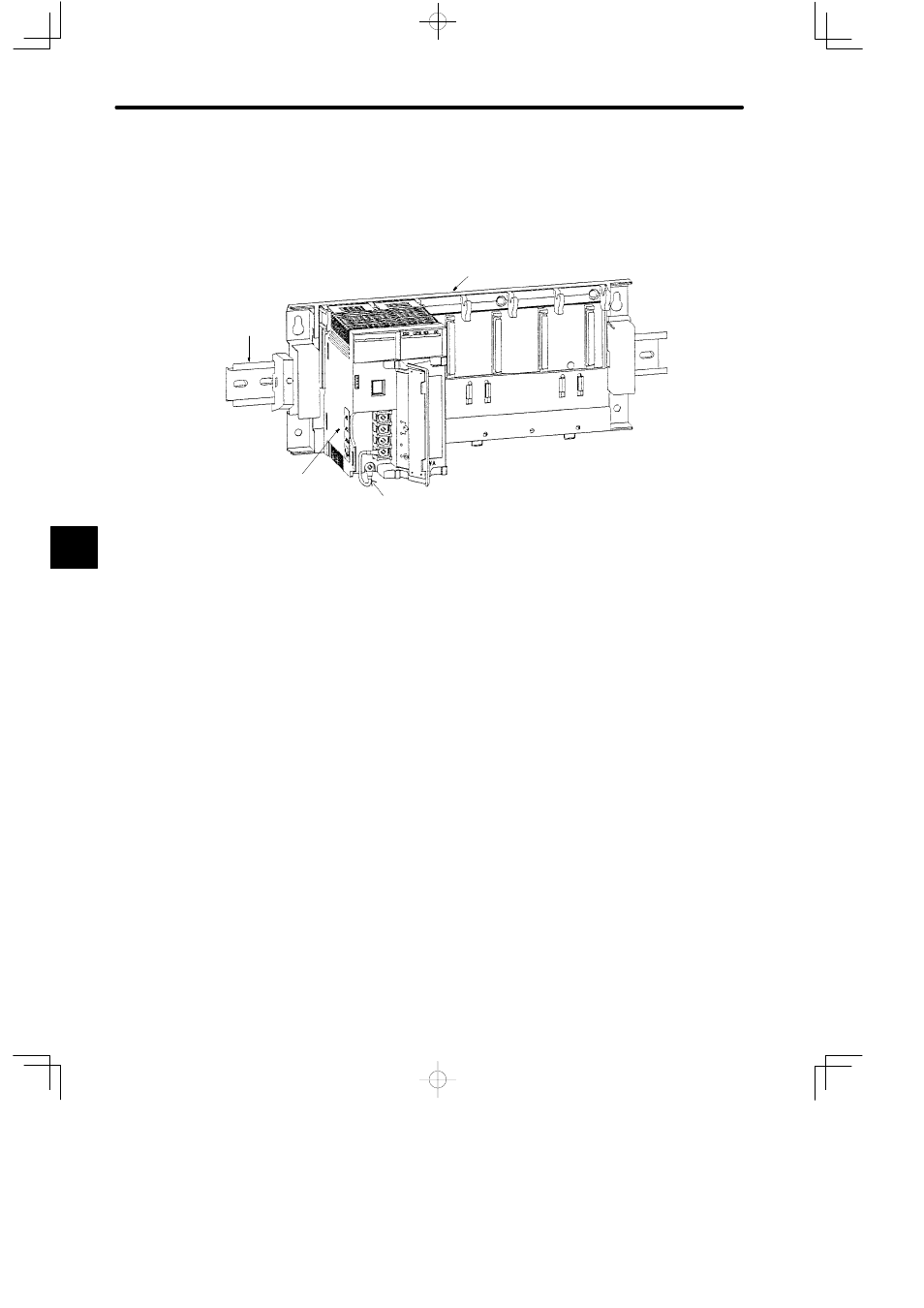
f) Improving Noise Immunity of the GL120 or GL130
Note
To improve the noise immunity of the GL120 or GL130, connect the protective ground termi-
nal (FG) of the Power Supply Module to the module mounting screw with a 2.0 mm
2
wire
when installing the Power Supply Module on the Mounting Base.
Connect the protective ground terminal (FG) to the
module mounting screw with a 2.0 mm
2
wire.
DIN track
Mounting Base
Power Supply Module
5.2.2 Installing Modules
1) Module Installation Location
a) Install the following Modules on a Mounting Base. The procedures for installing these
Modules on the Mounting Base are described in 5.2.3 to 5.2.7 in this section.
(1) Power Supply Modules
(2) CPU Modules
(3) Communication Modules
(4) I/O Modules
(5) Special Purpose Modules
(6) Motion Modules
(7) Expander Modules
5