Yaskawa MEMOCON GL120 User Manual
Page 447
!
6.1
Power Supply Modules
— 6-9 —
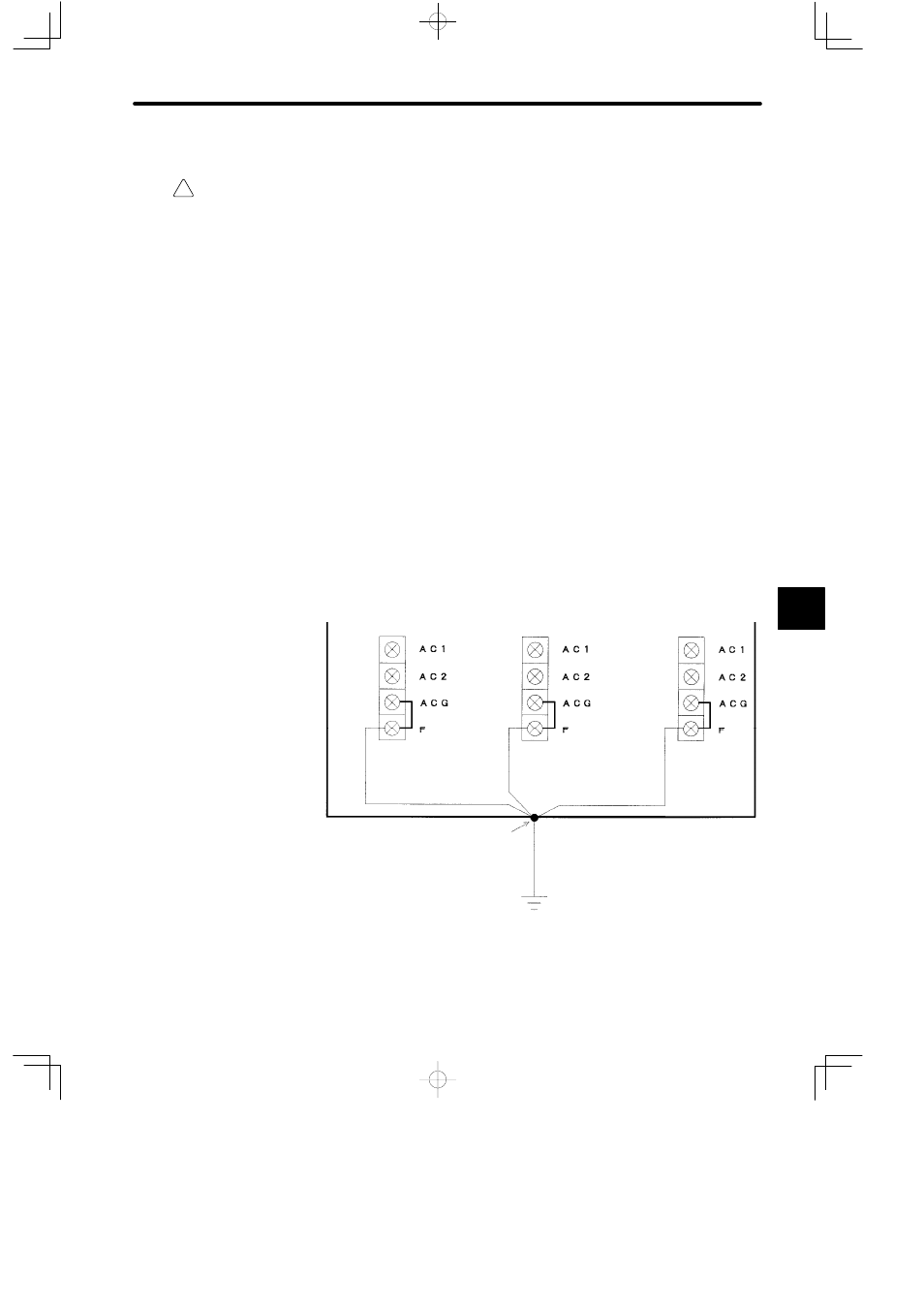
F. Functional Earth Terminal (FE)
Caution
Ground the functional earth terminal to a resistance of 100 Ω max.
Not grounding the functional earth terminal may result in electrical shock or malfunction.
1) Connect the functional earth terminal (FE) and the ground terminal of the control panel
with 1.5 mm
2
(AWG16) to 2.5 mm
2
(AWG13) wire (in-panel ground cable).
2) If more than one Power Supply Module is used, do not cross-wire between the functional
earth terminals. Connect the functional earth terminal of each Power Supply Module to
the ground terminal of the control panel separately.
3) M4 Phillips screws are used on the functional earth terminals. Accordingly, use solder-
less terminals for M4 Phillips screws for the in-panel grounding wire ends.
G. Grounding Control Panel
1) Connect the ground terminal of the control panel to a ground pole with a wire (outside-
panel ground cable) of 8 mm
2
(AWG 8) or larger. Make sure that the length of this ground
cable is as short as possible.
2) Use a ground pole with a resistance of 100 Ω max. Do not use the same ground cable
and/or ground pole with other strong electrical equipment.
In-panel
ground cable
Control panel
Ground terminal (E)
Field wiring terminal of
Power Supply Module
Field wiring terminal of
Power Supply Module
In-panel
ground cable
In-panel
ground cable
Outside-panel
ground cable
Field wiring terminal of
Power Supply Module
Ground pole (with a resistance
of 100 Ω max.)
E
E
E
6