Yaskawa MEMOCON GL120 User Manual
Page 236
System Components: Functions and Specifications
4.4.10 Distributed I/O Driver Module cont.
— 4-180 —
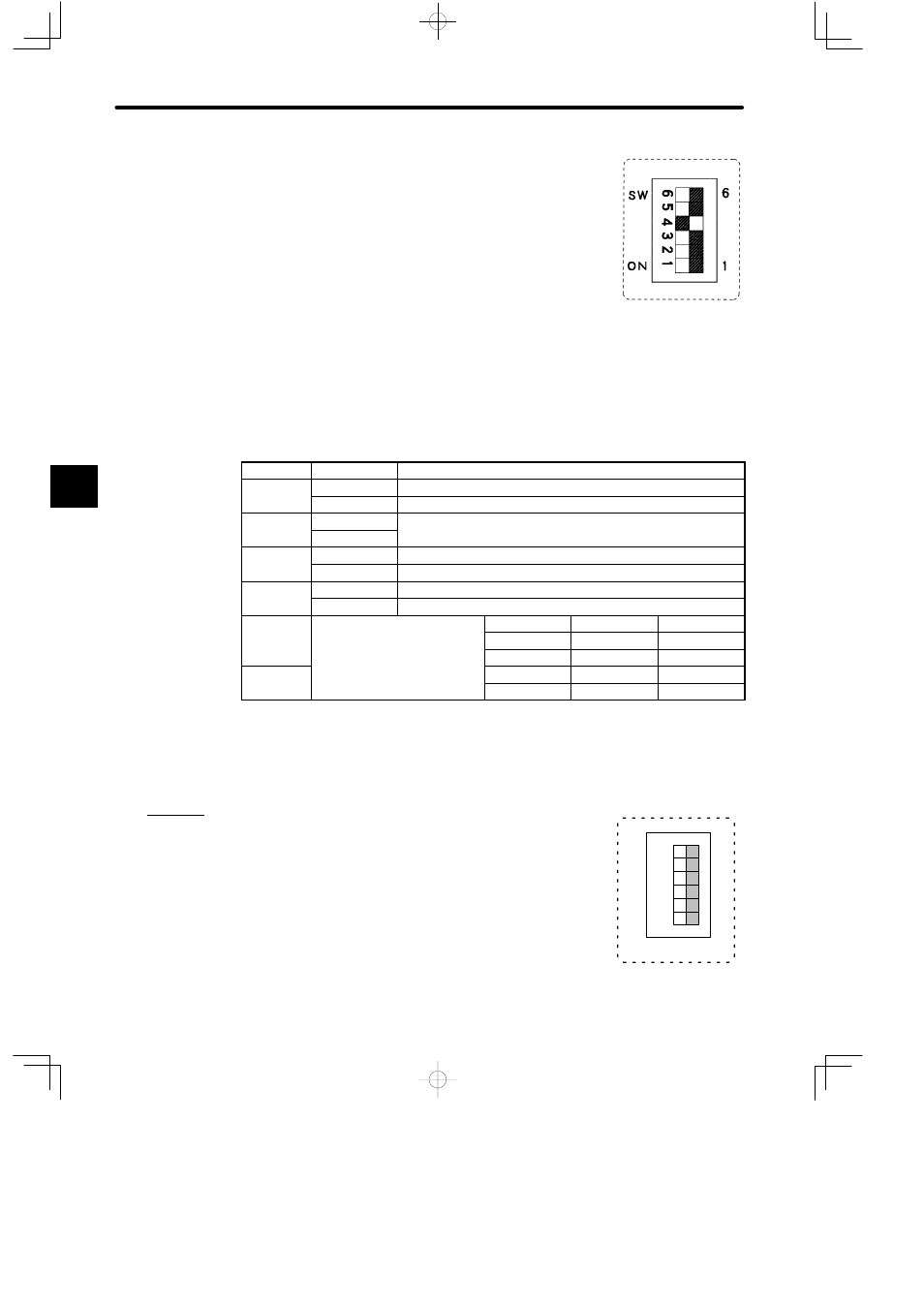
5) DIP Switch
a) The DIP switch consists of 6 pins. The pins are numbered
from 1 to 6 as shown in the diagram.
b) Each pin is turned ON when pressed to the left.
c) Each pin becomes effective at the following times.
(1) When the reset switch is pressed.
(2) When power is supplied to the Power Supply Module on the rack on which the
Distributed I/O Driver Module is mounted.
d) The function of each pin is shown in the following table.
Table 4.74 Function of DIP Switch
Pin
Setting
Function
1
ON
Internal terminator (terminating resistor) is connected.
OFF
Internal terminator (terminating resistor) is not connected.
2
ON
For future use. Set this pin to OFF.
OFF
p
3
ON
Sets Module to Self-diagnosis Mode.
OFF
Sets Module to RUN Mode.
4
ON
Input data is held when a communications error occurs.
OFF
Input data is cleared to 0 when a communications error occurs.
5
Sets the baud rate of the VINUS
I/O S
h
h
Pin 5
Pin 6
Baud rate
I/O System as shown at the
right
OFF
OFF
4 Mbps
right.
ON
OFF
For future use.
6
OFF
ON
For future use.
ON
ON
For future use.
Note
Always set DIP switch pin 3 to OFF. If the Module is used while pin 3 is ON, it may cause an
output error.
e) Examples of setting the DIP switch are shown below:
Example 1
When the DIP switch is set as shown in the diagram on the right,
the Distributed I/O Driver Module is set as follows:
• Internal terminator is not connected.
• Normal RUN mode
• Clear mode
• 4 Mbps
4
A
EXAMPLE
"
2
3
4
5
6
6
1
SW
ON
1