Yaskawa MEMOCON GL120 User Manual
Page 451
6.2
I/O Modules
— 6-13 —
Note
Module description are different depending on the Modules as follows.
Model No.
Module description
JAMSC-120DAI54309
120DAI54309
JAMSC-120DAI74309
120DAI74309
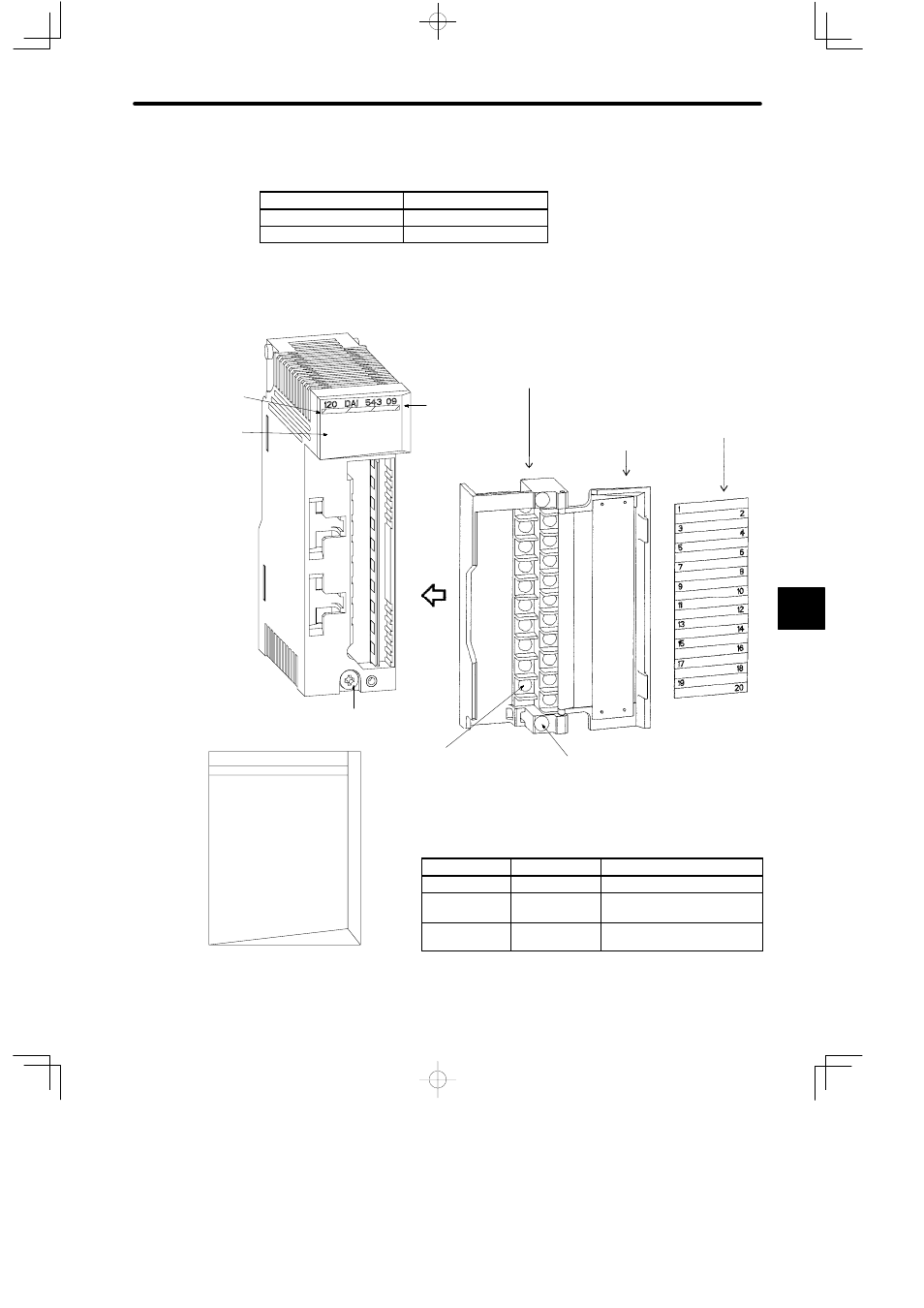
2) The following figure shows the appearance of the next three types of Output Modules:
−100-to 120-VAC or 200-to 240-VAC, 16-point Output Module (JAMSC-120DAO84309)
−100-to 120-VAC or 200-to 240-VAC, 8-point Output Module (JAMSC-120DAO83009)
−Relay Contact 16-point Output Module (JAMSC-120DRA84309)
Color code
(red)
LED area
Removable terminal block
for field connections
Hinged terminal
cover
Signal label insert
Module description
(120DAI84309)
Module mounting screw
(Use M4 Phillips screwdriver.)
Field wiring terminal
(Use M3 Phillips screwdriver.)
Terminal block mounting screw (Black)
(Use M3 Phillips screwdriver.)
LED
Color
Indication when ON
ACTIVE
Green
Processing input/output.
F
Red
Fuse broken, or external
power supply not connected.
1 to 16
Green
The corresponding LED is lit
when the input signal is ON.
Figure 6.6 Appearance of 100-to 120-VAC 16-point Output Module
LED area
120 DAI 843 09
ACTIVE
1
2
3
4
5
6
7
8
F
9
10
11
12
13
14
15
16
6