3 one-axis motion module, Appearance – Yaskawa MEMOCON GL120 User Manual
Page 313
4.7 Motion Modules
— 4-257 —
4.7.3 One-axis Motion Module
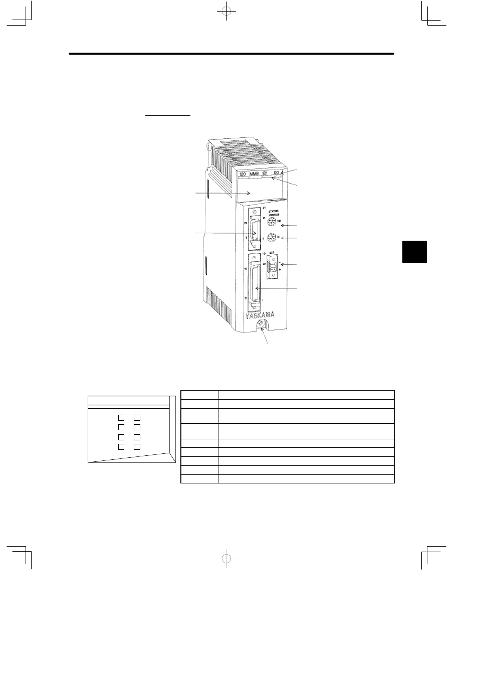
1. Appearance
Color code (yellow)
LED area
Module Description
(120MMB10100)
Rotary switch 1
Battery connector
I/O signal connector
Servo connector
Rotary switch 2
Module mounting screw
(Use M4 Phillips screwdriver.)
LED
Indication when ON
READY
Module has completed initialization and is ready.
ACTIVE
Module ladder instruction in CPU Module is ready to control the
Module.
RUN/E1
Module has completed initialization and is ready. (Same meaning
as READY).
FWD/E2
Module is outputting forward run command to servomotor.
RVS/E3
Module is outputting reverse run command to servomotor.
COIN/E4
Current position is in the positioning completed range.
PHA/E5
Module is detecting A-phase pulse of encoder.
PHB/E6
Module is detecting B-phase pulse of encoder.
Figure 4.78 Appearance of One-axis Motion Module
4
RUN/E1
READY
120 MMB 101 00
FWD/E2
RVS/E3
ACTIVE
COIN/E4
PHA/E5
PHB/E6
LED area