Yaskawa MEMOCON GL120 User Manual
Page 188
System Components: Functions and Specifications
4.4.5 MEMOBUS Modules (RS-232) cont.
— 4-132 —
e) COM Instructions(COMM, COMR)
Note
(1) The communications instruction used for MEMOBUS ports of the MEMOBUS Module
(RS-232) is the COMM instruction.
(2) The COMR instruction cannot be used for MEMOBUS ports of MEMOBUS Modules
(RS-232). This communications instruction can used only for MEMOBUS ports of Re-
mote I/O Receiver Modules.
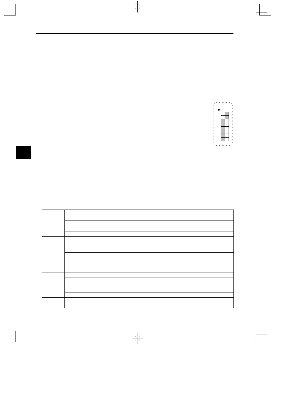
4) DIP Switch
a) The DIP switch consists of 8 pins. The pins are numbered from 1
to 8 as shown in the diagram at the right.
b) Each pin is turned ON when pressed to the right.
c) The settings of the pins are effective (read) at the following times:
(1) Pins 1 to 6: When the pin is turned ON.
(2) Pins 7 and 8: When the reset switch is pressed or when power is turned ON to the
Power Supply Module of the Rack where the MEMOBUS Module (RS-232) is
mounted.
d) Each pin’s function is shown in the following table.
Table 4.57 Function of DIP Switch
Pin No.
Settings
Function
1
ON
Sets communications mode and parameters of Port 2 to the defaults.
OFF
Sets communications mode and parameters of Port 2 to user settings.
2
ON
Sets communications mode and parameters of Port 1 to the defaults.
OFF
Sets communications mode and parameters of Port 1 to user settings.
3
ON
When using Port 2 as master port, sets communications mode to transparent mode.
OFF
When using Port 2 as master port, sets communications mode to MEMOBUS mode.
4
ON
When using Port 1 as master port, sets communications mode to transparent mode.
OFF
When using Port 1 as master port, sets communications mode to MEMOBUS mode.
5
ON
Sets Port 2 as slave port. Master communications become ineffective.
OFF
Sets Port 2 as combined master/slave port. Master communications become effective. When
using COMM instruction for Port 2, turn this pin OFF.
6
ON
Sets Port 1 as slave port. Master communications become ineffective.
OFF
Sets Port 1 as combined master/slave port. Master communications become effective. When
using COMM instruction for Port 1, turn this pin OFF.
7
ON
Sets Module number to 2.
OFF
Sets Module number to 1.
8
ON
Sets Module to self diagnosis mode.
OFF
Sets Module to normal operation mode.
4
12
345678
O
N