14 optical/electrical conversion module, Appearance – Yaskawa MEMOCON GL120 User Manual
Page 265
4.4 Communications Modules
— 4-209 —
4.4.14 Optical/Electrical Conversion Module
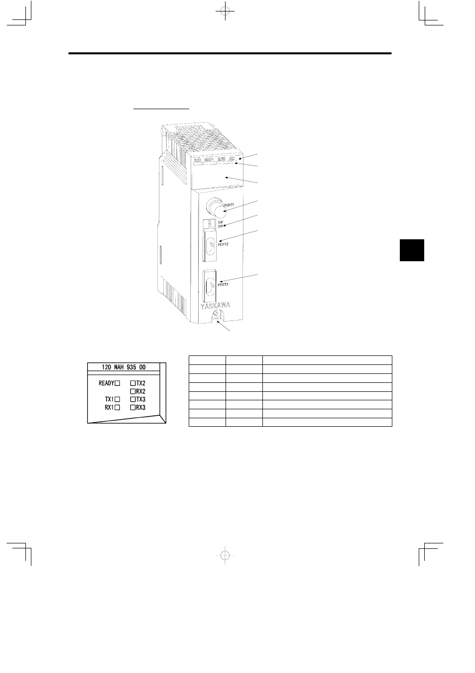
1. Appearance
Module description
Color code (yellow)
LED area
Electrical port (PORT1)
DIP switch
Optical port 1 (PORT2)
Optical port 2 (PORT3)
Module mounting screw
(Use M4 Phillips screwdriver.)
LED
Color
Meaning when ON
READY
Green
Module is operating normally.
TX1
Green
Module is sending data from electrical port.
RX1
Green
Module is receiving data from electrical port.
TX2
Green
Module is transmitting data from optical port 1.
RX2
Green
Module is receiving data from optical port 1.
TX3
Green
Module is transmitting data from optical port 2.
RX3
Green
Module is receiving data from optical port 2.
Note
The Module is not sending or receiving data normally if the LEDs TX1 to TX3 and RX1 to RX3
are all OFF.
Figure 4.62 Appearance of Optical/Electrical Conversion Module
4
LED area