Yaskawa MEMOCON GL120 User Manual
Page 374
5.2 Installing Mounting Bases and Modules
— 5-17 —
Note
(1) The device mounting steel plate to which the Mounting Base is to be installed must
have an integral (one-piece) structure.
(2) If the device mounting steel plate is coated, always peel off the coating around each
mounting bolt hole before installing the Mounting Base. This improves the noise immu-
nity of the GL120 or GL130. Also, pay attention to mounting screws to ensure conduc-
tivity between the Mounting Base and the device mounting steel plate. If conductivity
between the Mounting Base and the device mounting steel plate is insufficient, the
GL120 or GL130 may malfunction.
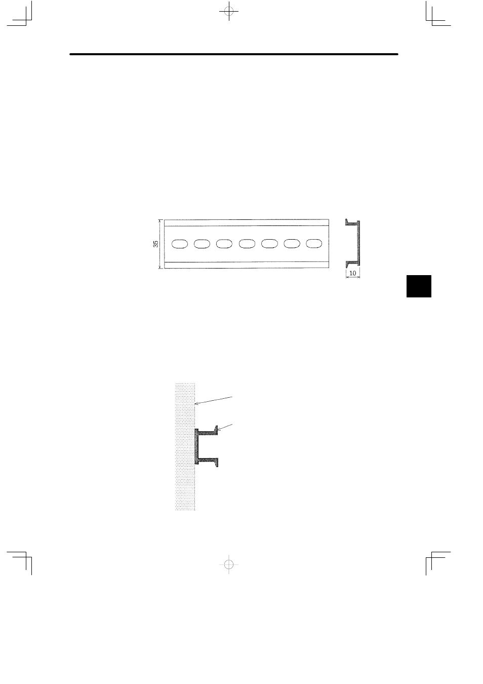
2) Installing Mounting Bases on DIN track
a) Use DIN track with a width of 35 mm and a height of 10 mm.
b) Determine the Mounting Base layout as described in 5.1.6 Mounting Base Layout.
c) Open DIN track mounting holes in the device mounting steel plate according to the
dimensional drawing of Mounting Bases shown in B.8 Mounting Bases. A.2 Drilling
Plan shows an example.
d) Install the DIN track on the device mounting steel plate as shown below.
Device mounting steel plate
DIN track
5