2 battery module, Appearance – Yaskawa MEMOCON GL120 User Manual
Page 339
4.8
Other Module
— 4-283 —
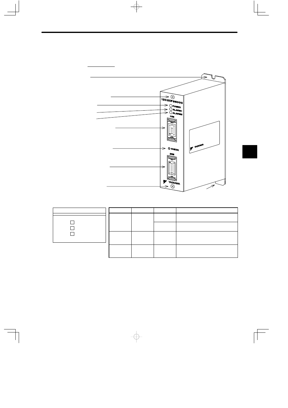
4.8.2 Battery Module
1. Appearance
Front panel mounting screw
POWER indicator
ALARM1 indicator
ALARM2 indicator
External power supply/external
I/O connector (1CN)
Battery voltage check switch
Battery voltage output
connector (2CN)
Front panel mounting
screw
Mounting hole
Mounting hole
LED
Color
Status
Meaning
POWER
Green
Lit
Power supply (24 VDC) is being sup-
plied externally from 1CN.
Not lit
The voltage of the battery is being
checked.
ALARM1
Red
Lit
The battery voltage is less than
3.3 V. The status is indeterminate,
however, during a battery check.
ALARM2
Red
Lit
The battery voltage is less than
3.0 V. The status is indeterminate,
however, during a battery check.
Figure 4.87 Appearance of the Battery Module
Note
If the BAT Module’s ALARM1 indicator lights, be sure to replace the battery with an ER6VC3N
replacement battery within one week.
Delay in replacing the battery may result in loss of memory content (rotation data) in the
absolute encoder.
4
120 XCP 96000
POWER
ALARM1
ALARM2
LED area